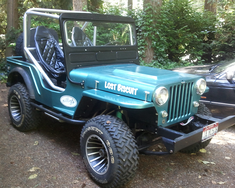
Over the weekend I completed the wiring along the engine. I wanted to hide the wires as much as possible, keep them as organized as possible, and not connect them to the fenders. Below are pictures of the lines run from the alternator, from the fan assembly (the wiring runs from the fan, over the radiator, and down along the grille to meet with the front light wiring) and then the wiring from the grille along the frame to the cowl.
This is the dual fan setup I purchased from North Coast Peformance, an eBay Power Seller. I fiberglassed the two fans together and built a metal frame to surround them and attach them to the radiator framework. This setup included a thermostat that slides snuggly inbetween the radiator fins. These two 10″ fans cover almost the entire radiator, making it a tight fit. However, between the aluminum radiator and the fans, I should have no overheating problems.

Ok, not the greatest pic. But, it will look cleaner once I organize the spark plug wires and trim the black tubing and the red wire that’s hanging over the valve cover.

You can see the tube that runs from the grille and under the header. The wiring from the fuel pump then merges into the black tube. Now, I have to drop the body on, cut the wires, and add a plug so that these wires easily connect/disconnect.

Hey Dave
Could you show a little more on the thermostat that slides snuggly inbetween the radiator fins? I would like to see what you did.
I looked up (Google) the Derale Thermostat Fan Controller Kit and it threads into AN Inlet. I don’t think this is the same thing as you got?
Here’s a link to the kit that came with my fans. http://cgi.ebay.com/ebaymotors/DERALE-FAN-TEMP-CONTROLLER-SWITCH-THERMO-PROBE-16738_W0QQitemZ230304505243QQcmdZViewItemQQimsxZ20081031?IMSfp=TL081031104001r4459. Note the image (http://i11.ebayimg.com/03/i/000/fb/0e/261f_1.JPG). The black cylinder with two black wires coming out of it and the ‘caution’ label is half the sensor. The other half is the long golden probe in the bag. The long golden probe is screwed onto the black cylinder, then the probe is gently worked between the radiator fins until it protrudes out the other side of the radiator. Finally, a little clasp is put onto the protruding part of the probe that keeps it from backing out of the radiator.
I’ll try and get a couple pics later today.
– Dave
Pingback: Specs of My Build | eWillys