emailNeed to contact me and don't have my email? Click on email button.
About eWillys
Welcome to eWillys.com, a website for vintage jeep enthusiasts. I update this website nearly every day with jeep deals, jeep history, interesting reader projects, jeep related info, and more.
These quick searches can help you find things on eBay. People list in the wrong categories all the time, so don't be surprised to see brochures in the parts area for example. This section used to be split into jeeps, parts and other categories, but recent changes to eBay will require this information to be recoded.
The links to posts below show jeeps grouped by models, condition, and other ways. Some of these jeeps are for sale and others have been sold. If you are unsure whether a vehicle is still for sale or not, email me at d [at] ewillys.com for more info.
Importantly, the allure of buying a project jeep can be romantic. The reality of restoring a jeep can be quite different, expensive and overwhelming without the right tools and resources. So, tread carefully when purchasing a "project". If you have any concerns about buying a vintage jeep, or run across a scam, feel free to contact me for help, comments or concerns .
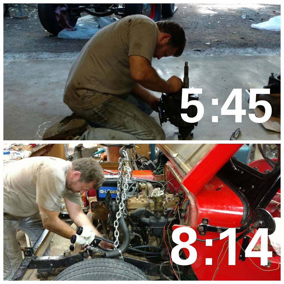
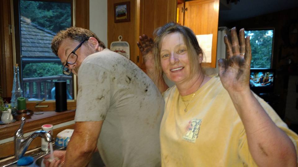
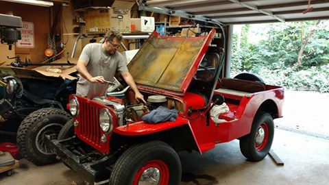
My wife spent her second-birthday helping me in the garage (The 25th of June is the day of her bombing .. she says it was like a whole new life after that). She’s a great help; she does any task asked without complaint. I couldn’t ask for a better co-mechanic!
It’s late, so I’ll make this short. We made good progress today. We installed the vacuum holding tank, installed the passenger seat, bled the brakes, rewired some of the frayed wires, connected the transmission and engine, and slid the power train back into place. Now we just have to re attached some wires, hoses, and tighten a few things and we’ll get to test it. Here are a few
pics:
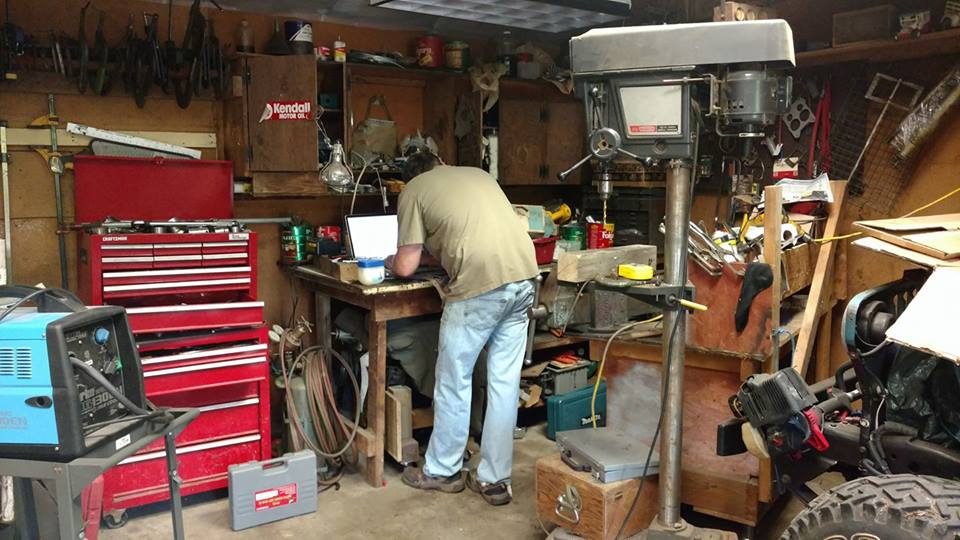
It’s hard to leave the computer, even in the garage!
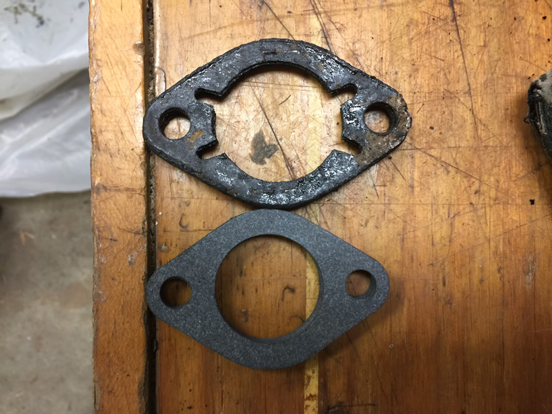
A couple things confused me today. In this first example, we have at top the original gasket between the intake manifold and carb. On the bottom is the replacement gasket included in a rebuild kit. As you can see, it won’t work. Is the DJ-3A intake that unique? I know it uses a Carter YF 2392, so that’s unique.
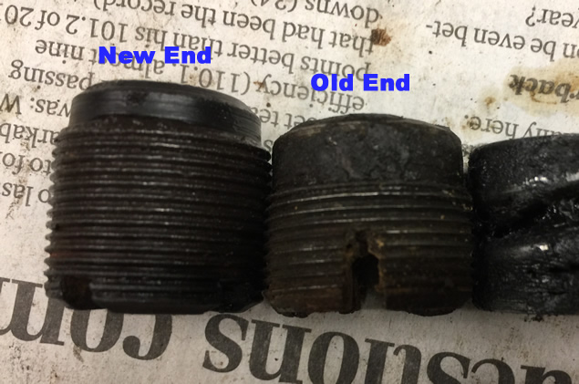
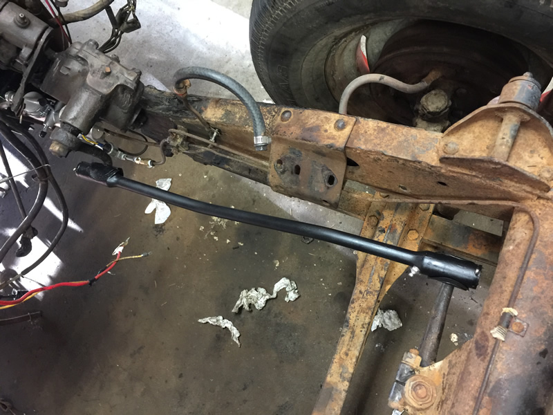
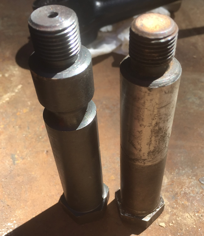
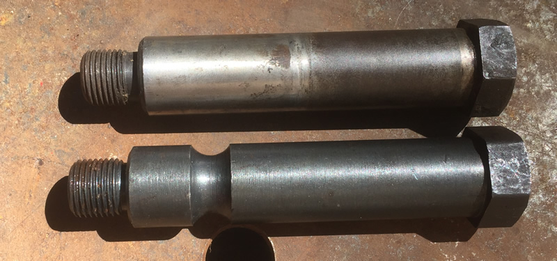
Next up, the ends for the dragline. On the left is the new end and on the right the old one. The new one is taller and has shallower slots for installing it. The old end is shorter and has much deeper slots (those deeper slots are really helpful) . Anyone know why these are so different? Between the longer end and longer springs, I couldn’t put all the parts together around the bell crank arm (and I tried). In the end I was forced to use some old and some new parts.
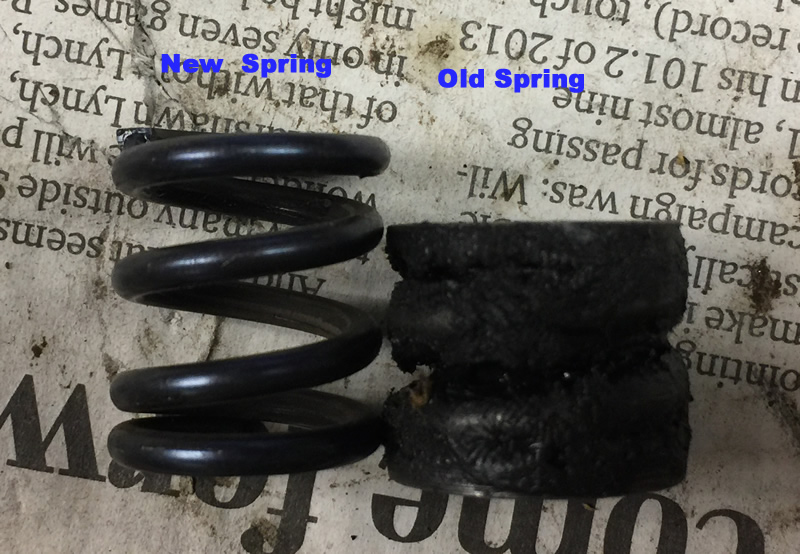
Note the difference in the spring heights. Try as I might, I could not compress the spring enough to install an end. I changed to the old end.
Once I used some of the old parts, I was able to get the draglink installed.
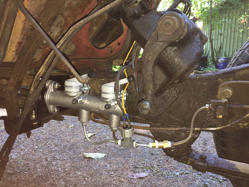
I also installed the dual master cylinder. The rear brake line connected perfectly. I just had to add one bend. The front brake lines were a big problem. You’d think trying to locate an 3/16-1/4 adapter would be easy, but it turned into multiple trips to the auto store, where I hunted for the right sizes with the right threads. The staffs at two different auto stores were not useful (nice, but not helpful). So, this will work for now, but I’d like to get the proper adapter and remove the connectors and line on the right side.
Sunday morning we’ll 1) bleed the brakes and then, if all goes well with that, 2) replace the front springs and then 3) drop in the engine.
Someone on Facebook the other day claimed that DJ-3As were made from surplus parts. As with any model during those years, there were some DJ parts used on other models. But, as with other models, there are parts unique to the DJ-3A and I’m learning more about them daily, one part at a time.
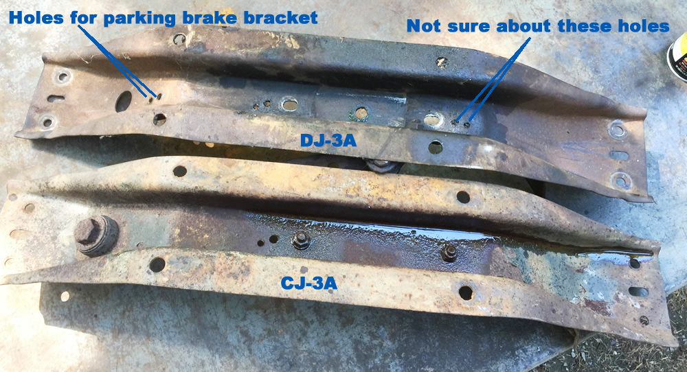
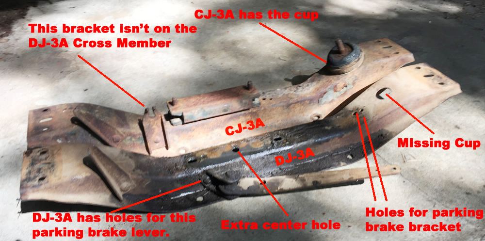
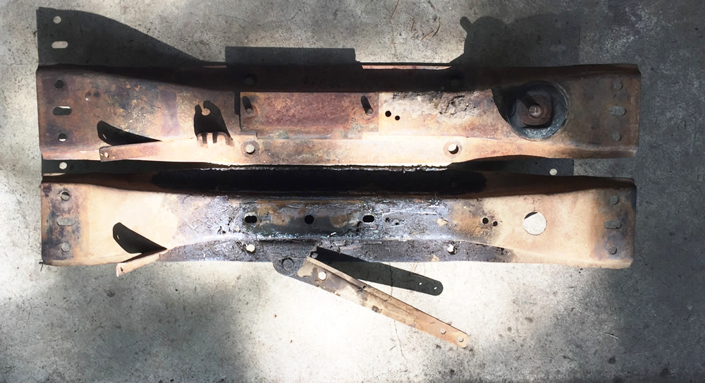
Today I spent time working on the transmission crossmember. Because finding a DJ-3A crossmember was near impossible (and since Rusty did not have a normal crossmember), I got a CJ-3A crossmember from Chris McKay for Rusty. But, I’ve decided to use the stock DJ-3A crossmember off of Patterson on Rusty and keep that jeep as stock as possible, and DJ-3A-matize the 3A crossmember for Patterson. Here are a couple pics:
So, to make the CJ crossmember a DJ unit, I will have to remove the transfercase cup and drill several holes.
Unfortunately, as I disassembled Patterson’s crossmember I ran into a couple problems with the rubberized mount for the transmission. Here’s a look at what I pulled off of Patterson. Note how narrow the two holes are for mounting the rubber piece to the transmission (too narrow for a standard T-90 mount:
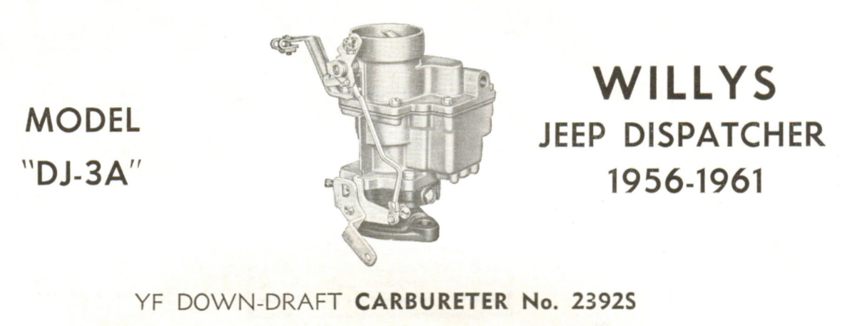
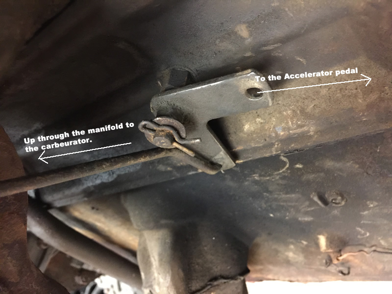
On Thursday evening I spent time moving parts from Patterson’s stock, but tired, DJ-3A engine to Rusty’s rebuilt M-38 engine so I could install it in Patterson. One item that caught my attention was Patterson’s DJ gas pedal linkage versus Rusty’s. Patterson’s appeared stock, while Rusty’s had a modified pivot point, probably the result of using the M-38 block. I decided to keep Patterson’s as it was and recreate the part for Rusty’s engine.
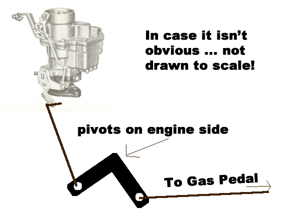
DJ-3A gas pedal Linkage: The linkage goes through the firewall to a pivot point on the driver’s side. When the gas pedal is depressed, a rod pushes an angle piece around a pivot, forcing a second rod upwards to a YF 2392S carb, causing the gas flow to increase.
Patterson’s real pivot piece (and it seems I misspelled carburetor in my pic).
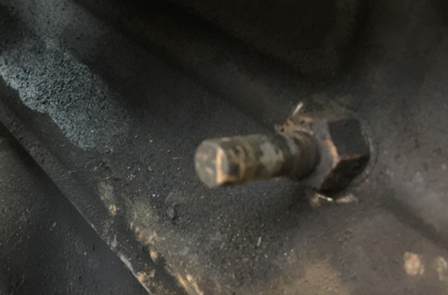
This shows the piece after removing the parts. The pivot bolt is solid on the end with a hole for a cotter pin.
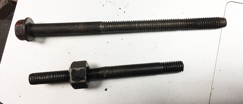
Example of what I removed from Rusty (bottom) and the bolt I will use to make a new one (top with new threads extended up it so I can add a bolt). The biggest problem with the custom piece at bottom is that it had no cotter pin. It was only held on by a bolt, which could have easily have come unscrewed as the gas pedal pivot piece moved back and forth. Continue reading →
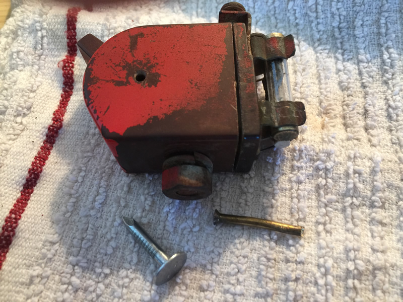
Patterson has a Harrison Heater, common in the early DJ-3As. Attached at the bottom of the dash is an Ark-Less four position switch (Off, Low, Medium, High) that controls the fan speed. The switch wasn’t delivering current, so I spent the day figuring out how to pull it apart and clean it up in the hopes that the switch could be resurrected.
The switch is held together by a long pin in the center. The switch also rotates on this pin. To remove the pin, the rounded edges on the pin must be drilled/pressed together/or someone modified. I chose to drill out the ends.
Here’s what it looks like to begin (not my switch .. I forgot to take this pic .. thanks to the cj-2a.com page)
Note the small hole. That pin must be pushed out
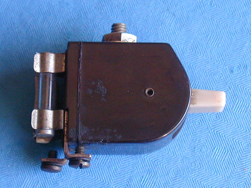
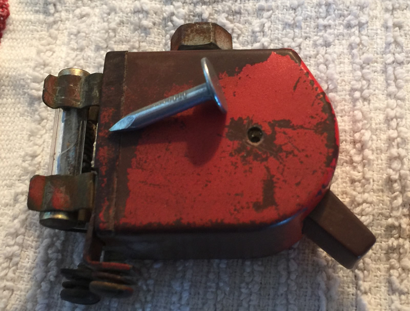
Now, here’s my switch. It received some paint when Patterson was repainted (I believe the paint was touched up some at some point). Once I drilled out the end of the pin a little, I used the nail to push the pin through.
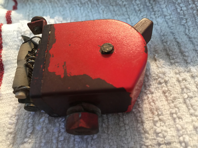
Here’s the other side of the pin. Now that it is sticking up, I can remove it.
Pin removed. I didn’t put much pressure on the pin when I first pushed it through, so I *think* the pin was already bent somehow.
We had a good day of work on Patterson today. First up, we confirmed that all the lights, blinkers, and even the hazards work. The brake lights don’t work yet, but that’s related to the master cylinder. I’ve ordered a dual master cylinder system from R&P, which ought to solve the brake issues.
The last electronic issue to debug is the heater motor. That’s on deck for tomorrow morning.
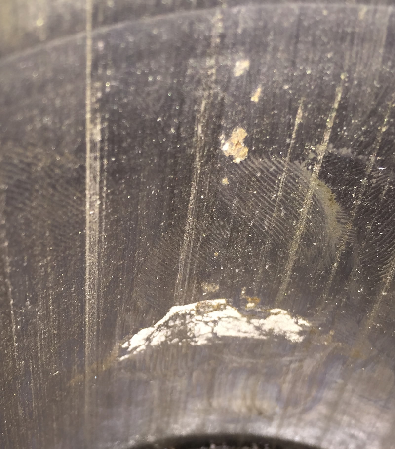
We took a look a closer look at Patterson’s engine and concluded it needs a full rebuild. There are multiple areas of pitting on the piston walls. Examples:
Wall of piston #4. Several instances of pitting.
Pitting on #2
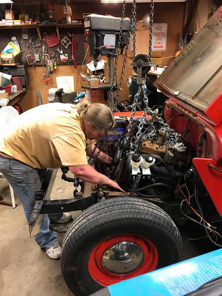
So, we turned our attention to Rusty’s engine, one that is marked as a rebuild. Ann tackled the cleaning of it. It was supposed to be a “good enough” job, which she surpassed.
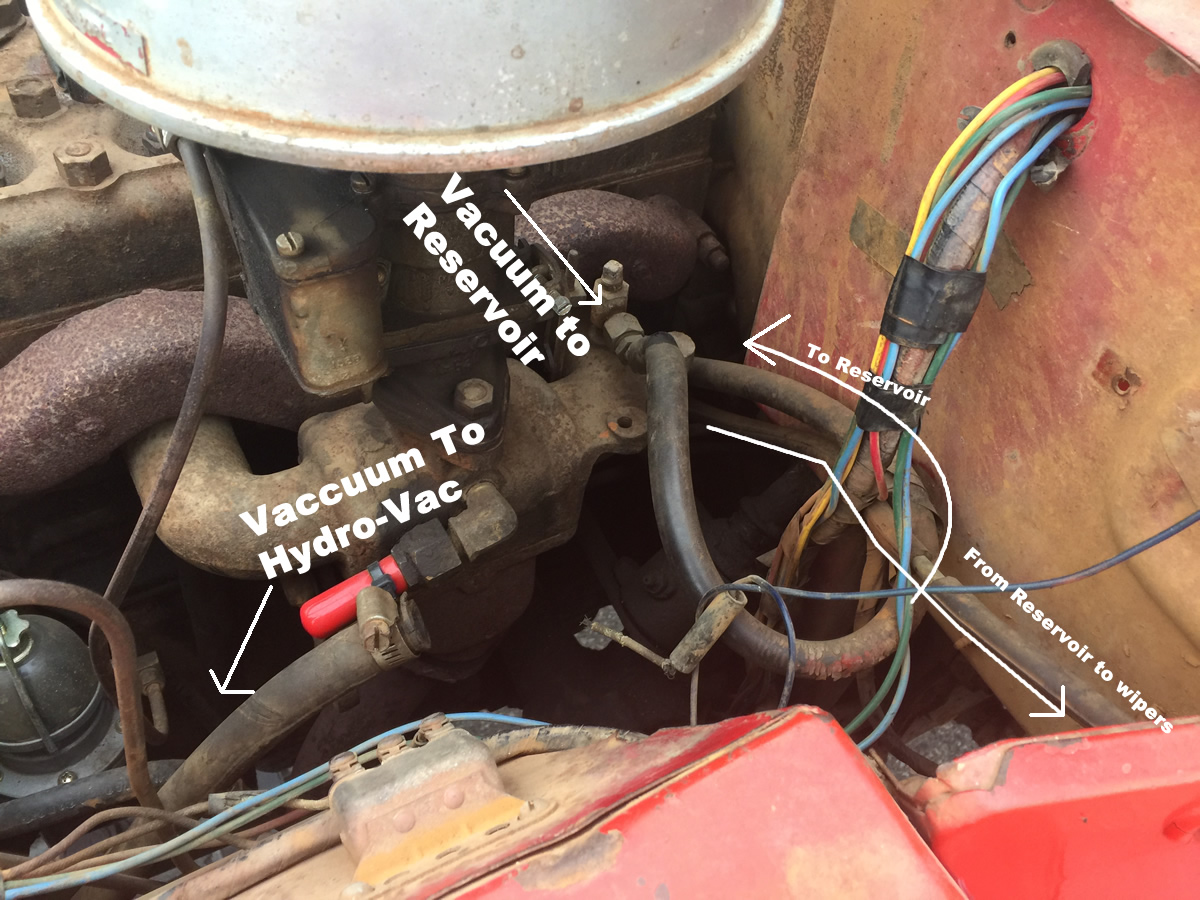
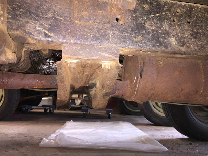
In case anyone’s curious, this is how Patterson’s vacuum reservoir is setup. Based on what I’ve read, a reservoir was important if running dual wipers. The vacuum begins at the manifold, then winds down under the body.
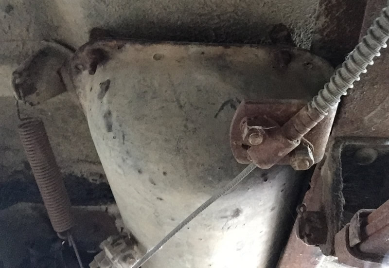
It winds up underneath to a reservoir tucked in between the frame and the spring for the parking brake.
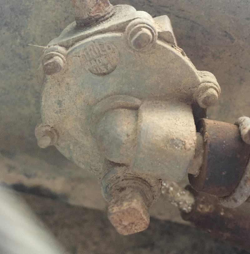
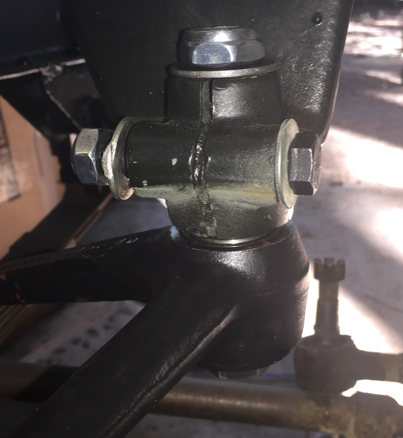
This is a close up look at the TRICO valve on the reservoir.
This is a not so perfect illustration of how it mounts. Because of the support channels on the floor of the body, the reservoir had to be shimmed down about an inch. The solution was a set of three nuts between the body and the reservoir. Continue reading →
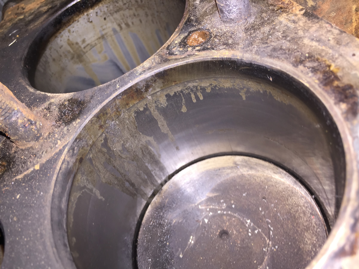
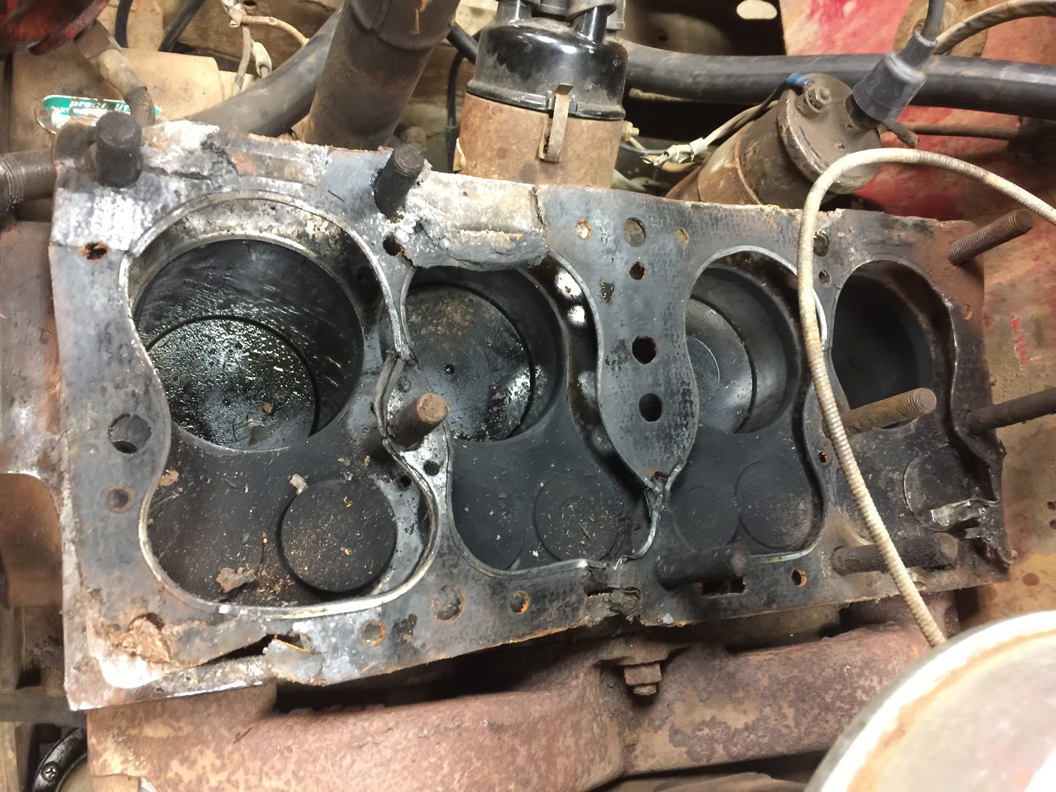
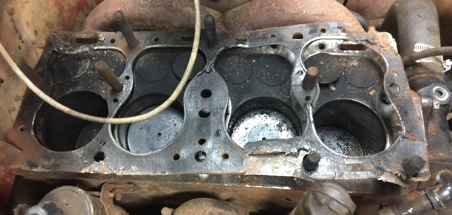
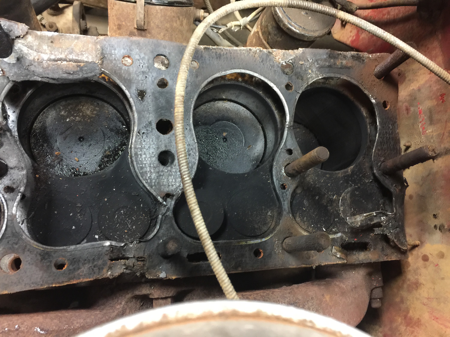
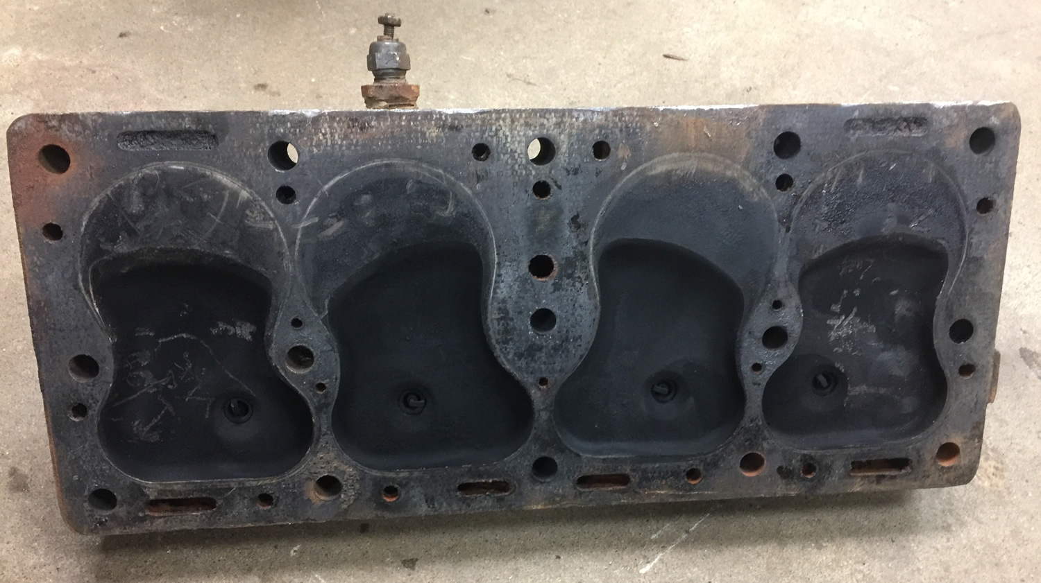
I pulled the head on Patterson last night. I don’t see any cracks in the block nor do I see any obvious signs of coolant, though there might be a tiny bit of residue on the tops of pistons 1 and 2. My initial reaction is that coolant is entering the oil elsewhere. The engine does appear to have a recently replaced water pump. Anyway installing that incorrectly would result in mixing coolant and oil??
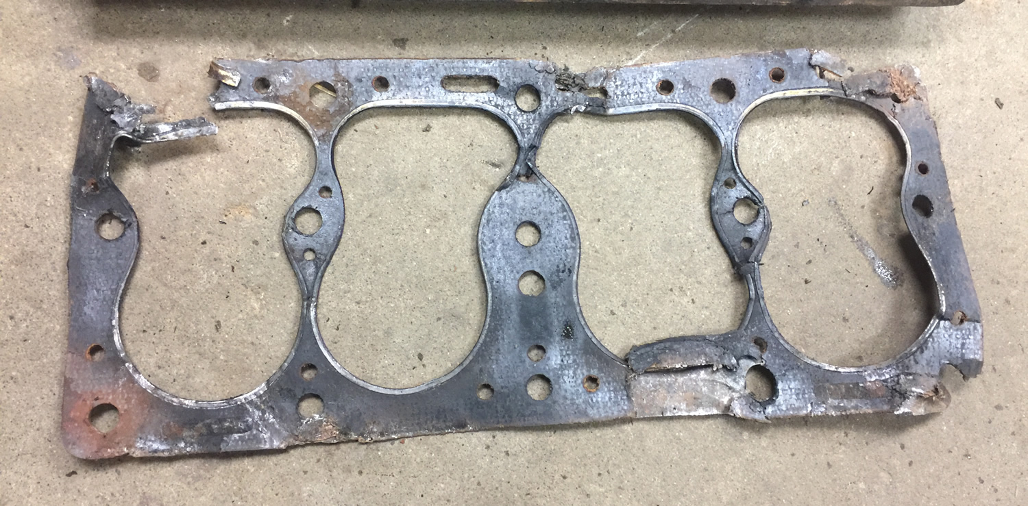
The first two photos show how the pistons and head gasket looked right after pulling it.
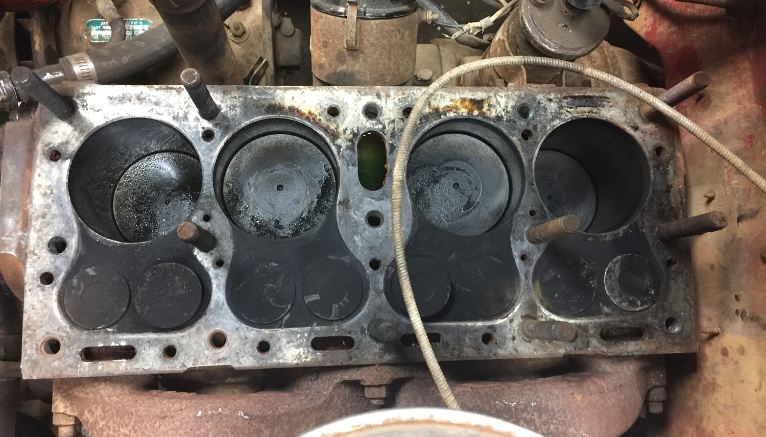
Then after pulling off the gasket and vacuuming up the dirt:
I made an puzzling discovery about bell cranks the other day. I ordered a rebuild kit for Rusty’s bell crank. When I began assembling it, I discovered the original and new bolts were different. So, I had to use my old bolt (which fortunately was in good shape). Going back online, all the bell crank rebuild kits show the left hand bolt below (anyone need a new bolt .. I don’t). Do any other jeeps use the shorter bolt in their bell cranks?
Both of the DJ-3As have the same setup. The bolts they use lack an indent (used to secure the bolt to the bell crank mount). They are slightly shorter and 1/16th larger in diameter than the replacement crank. The DJ bolt lacks the hole at the end.
Here it is reassembled. The horizontal bolt clamps the unit together, but does not anchor the bolt.
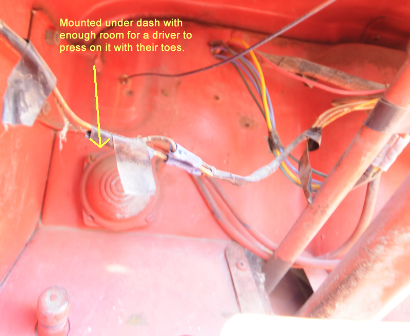
One unique feature that came with Patterson is this foot pump activated windshield sprayer. This is how the bag looked when we bought it. The top was corroded and the bag was empty and dirty. You can see the hose running from the top to the firewall.
Under the dash, the hose ran to the pump.
Here’s the whole system after the parts were cleaned up.
Unfortunately, the rubber on the pump isn’t any good. I found an NOS food pump on eBay that’s affordable, but would love to find the same pump again. Continue reading →
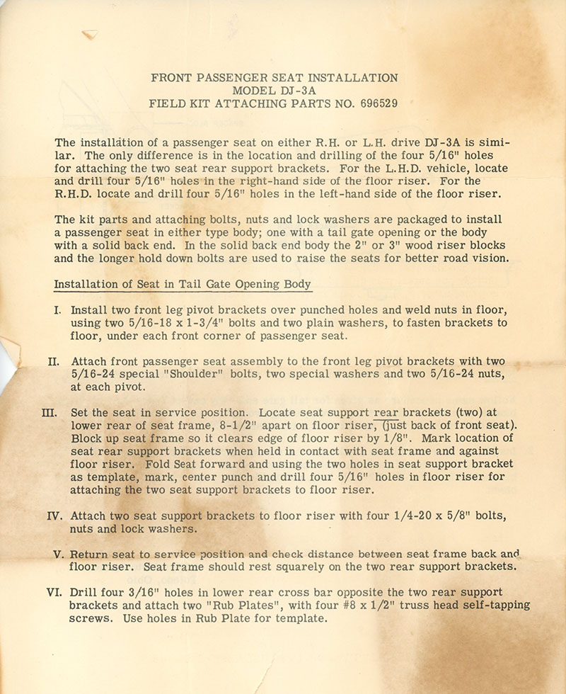
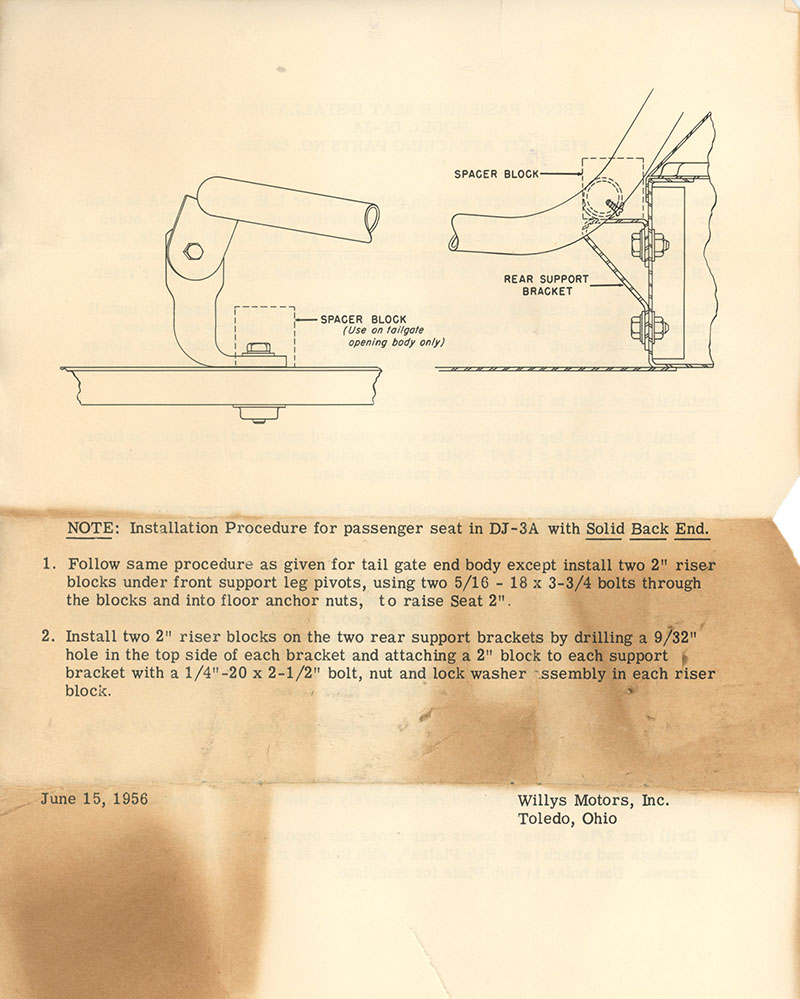
UPDATE II: Add are some instructions (thanks Terry!) for installing DJ-3A seats:
======================
ORIGINAL POST UPDATE MAY 2017: I’ve added a couple pics at the end and included a discussion on the extra channel DJ-3As have.
Last fall, when disassembling Rusty, I thought it was odd that the 2/3 1/3 seats had been mounted on wood blocks. I assumed this had been done by the previous owner to raise the seats.
Yesterday, I discovered that Patterson’s passenger seat was loose. When I examined it more carefully, I learned that it was loose because one of the wood blocks under the seat had broken. I can only conclude that all DJ-3A’s with 2/3 1/3 seats were mounted on wood blocks? Or maybe only the early ones?
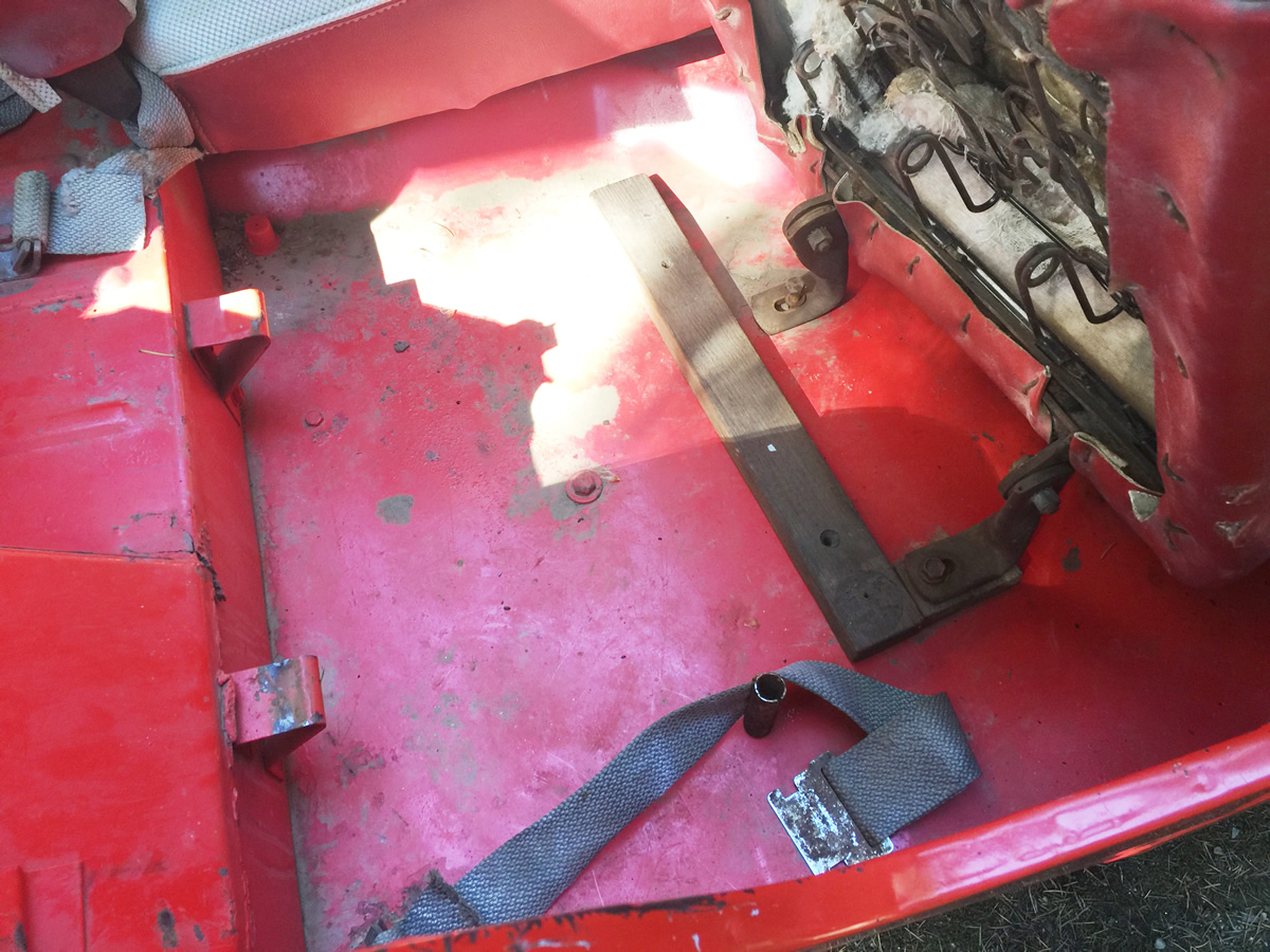
The photo below shows the passenger seat tilted forward. The front of it is mounted in a way that allows it to pivot forward. The mounts are bolted through a piece of wood, then through a piece of cloth, through the body, and into a welded bolt. The rear of the seats rests on the two mounts at the back of the well. The long piece of wood is a well-seasoned (at least 45 years old) and stained piece of oak that will work perfect for replacement blocks.
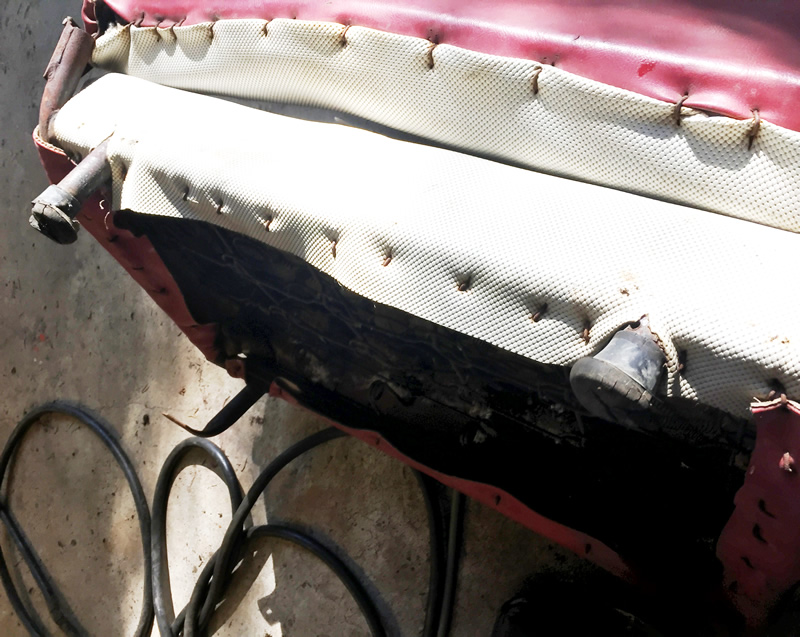
Unlike the passenger seat, the rear of the driver’s seat rests on two posts; slide onto the ends of the posts are rubber feet. Those rubber feat sit on blocks of wood also.
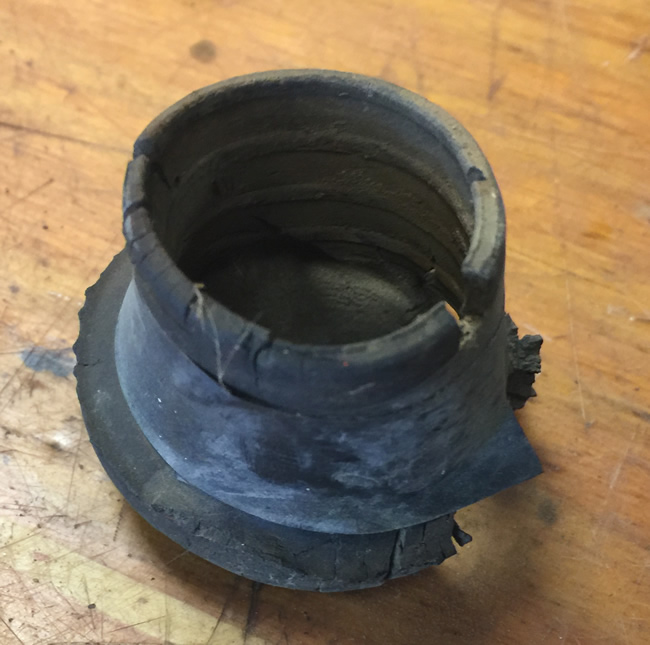
A close up of the rubber foot. The hole is 1 inch in diameter, so I ought to be able to find rubber feet to replace these tired ones.
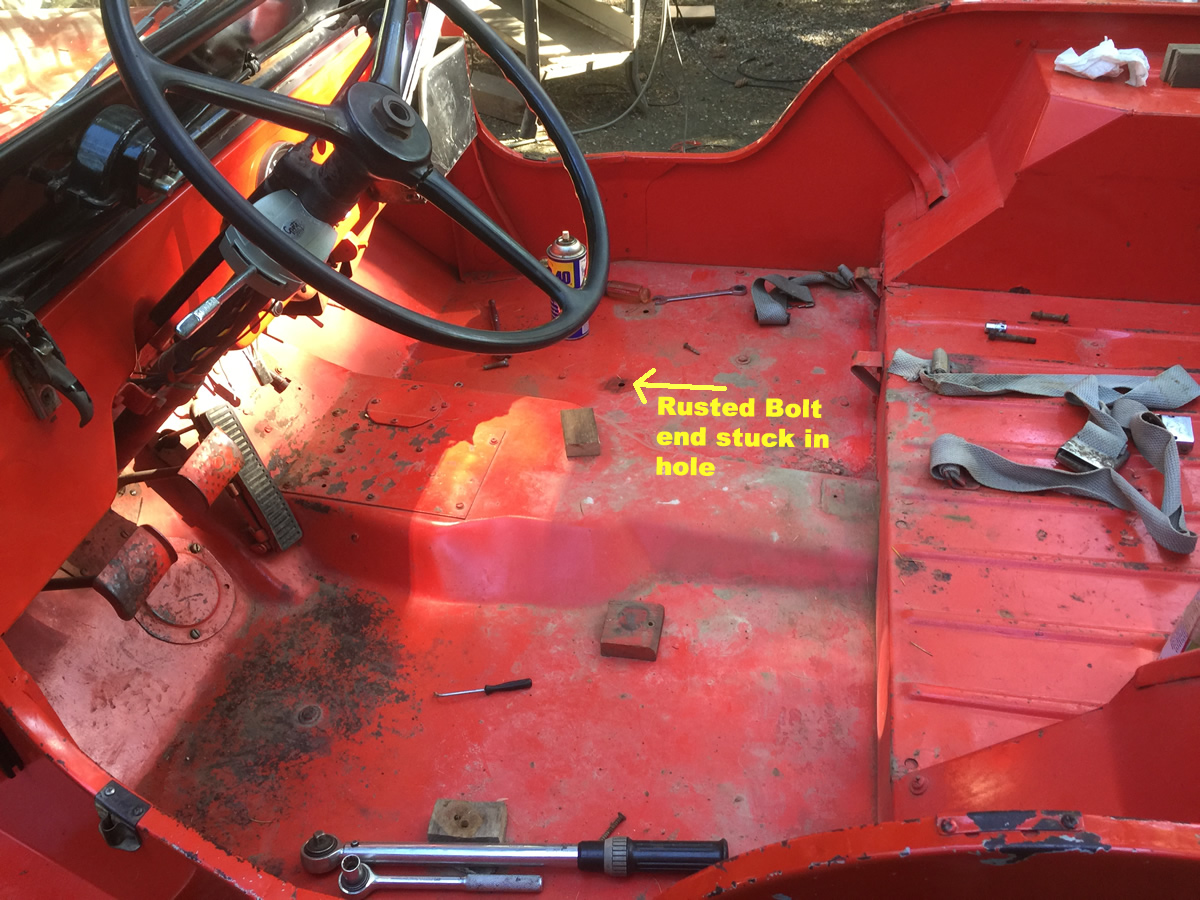
This shows how great the floor on this DJ is.
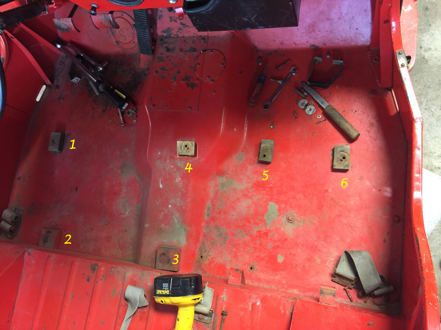
Another angle. Blocks 1, 4, 5, and 6 were the same size. Blocks 2 and 3 were larger and screwed down to the body. The rear 2/3’s seat rested atop those blocks.
I’ve drilled cut and drilled the blocks. They are ready for installation. I plan to add a thin piece of rubber under the blocks. Once I remove the rusted end of one bolt that broke, I’ll be able to reinstall the seats.
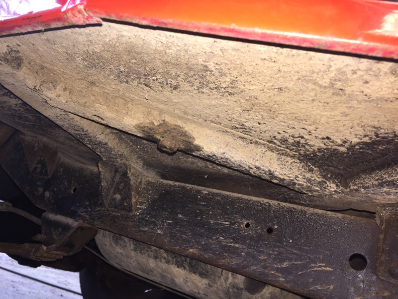
If you take a look at wood block #1 and block #6 there’s something curious. While the body area under wood block is similar to a CJ-3A, the body area under #6 has an additional channel (btw, we’ve yet to document any under DJ-3A body channels with wood in them).
This is the passenger side with the extra channel and a welded bolt.
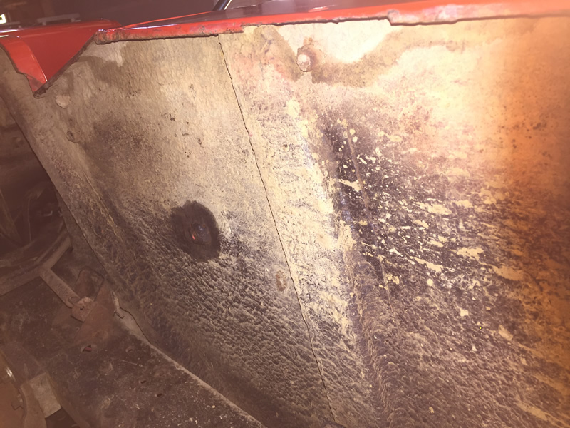
No channel on the driver’s side even though there is a bolt welded there.
Finally, the DJ-3As used wood blocks between the frame and transmission crossmember.
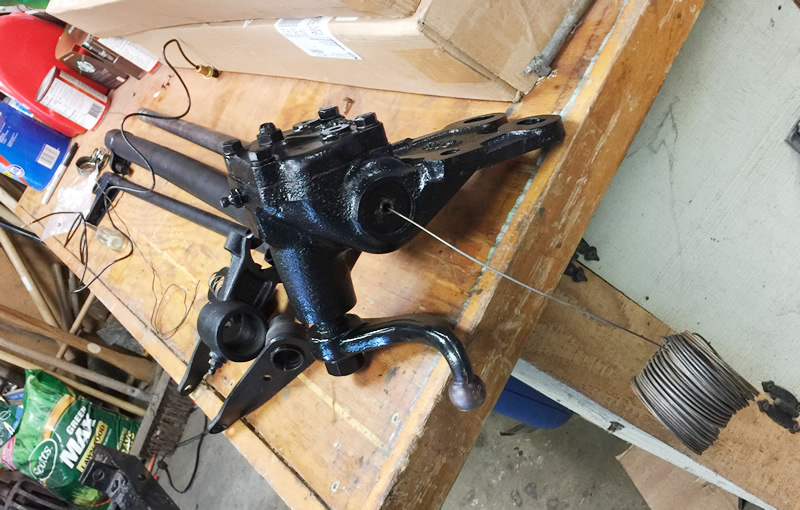
Yesterday I assembled Rusty’s column shifter. In my head, I took all kinds of photos. One in particular I took (again in my mind) showed the layout of all the parts prior to assembly. Alas, somehow that photo never made it onto my phone!
The DJ-3A shifter is slightly different from a VEC CJ-2A shifter. I can’t say how much it differs from a Jeepster or wagon column shifter. But, i can say that following these VEC CJ-2A instructions were very helpful.
After laying out the parts (and not taking a photo) I began the assembly process by learning how to install the horn wiring. After looking up how to do it on a 3B (thanks CJ-3B Page!), it turned out to be quite easy.
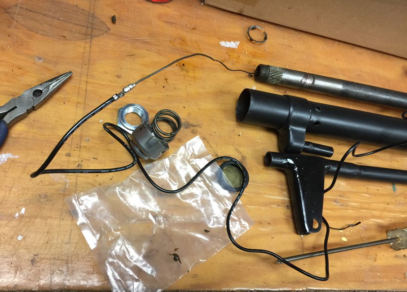
Step 1) Thread some of my grandfather’s wire through steering shaft.
Step 2) Attach the wire to the horn wire end. In this case, I ran it through wire connector and then bent it so that the wire would not pull back out of the connector.
Step 3) Pull the wiring carefully through the end of the shaft.
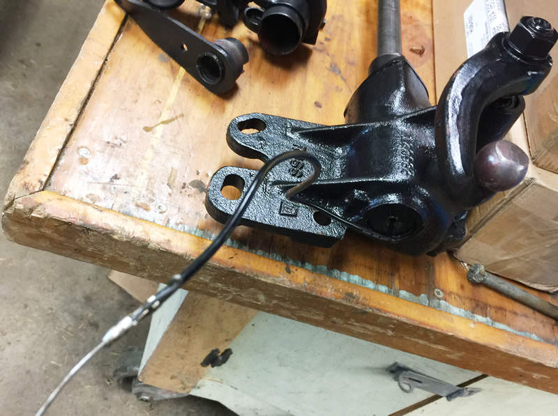
With the wire installed, next on the list was assembling the shifter. The first step involved installing a washer, a spring, and a second washer onto the column shift tube Next, the interior shift lever must be screwed onto the shift housing. Then, slide the shift housing onto the column shift tube, pushing it far enough up so that a special metal pin can be inserted. Once that is done, you have to weld the end of the tube to the pin to secure it.


