Paul-M38 Research Archives

To Top

Paul Finished His Stainless M-100 Trailer

• CATEGORIES: Builds, Features • TAGS: This site contains affiliate links for which I may be compensated.

As always, Paul’s detailed work has resulted in a work-of-art. Well done Paul!

Paul writes, “The earth has calmed down these last few months so I’ve made good progress on the M100 trailer rebuild. In fact, other than measuring the length necessary for the trailer safety chains and the electrical harness everything else is finished. While I still spent over 300 hours to build the stainless steel box and rebuild everything I planned on reusing it was easier than I’d anticipated. I had no idea I’d need so many 2X4’s but the local Home Depot store was happy to take my money.

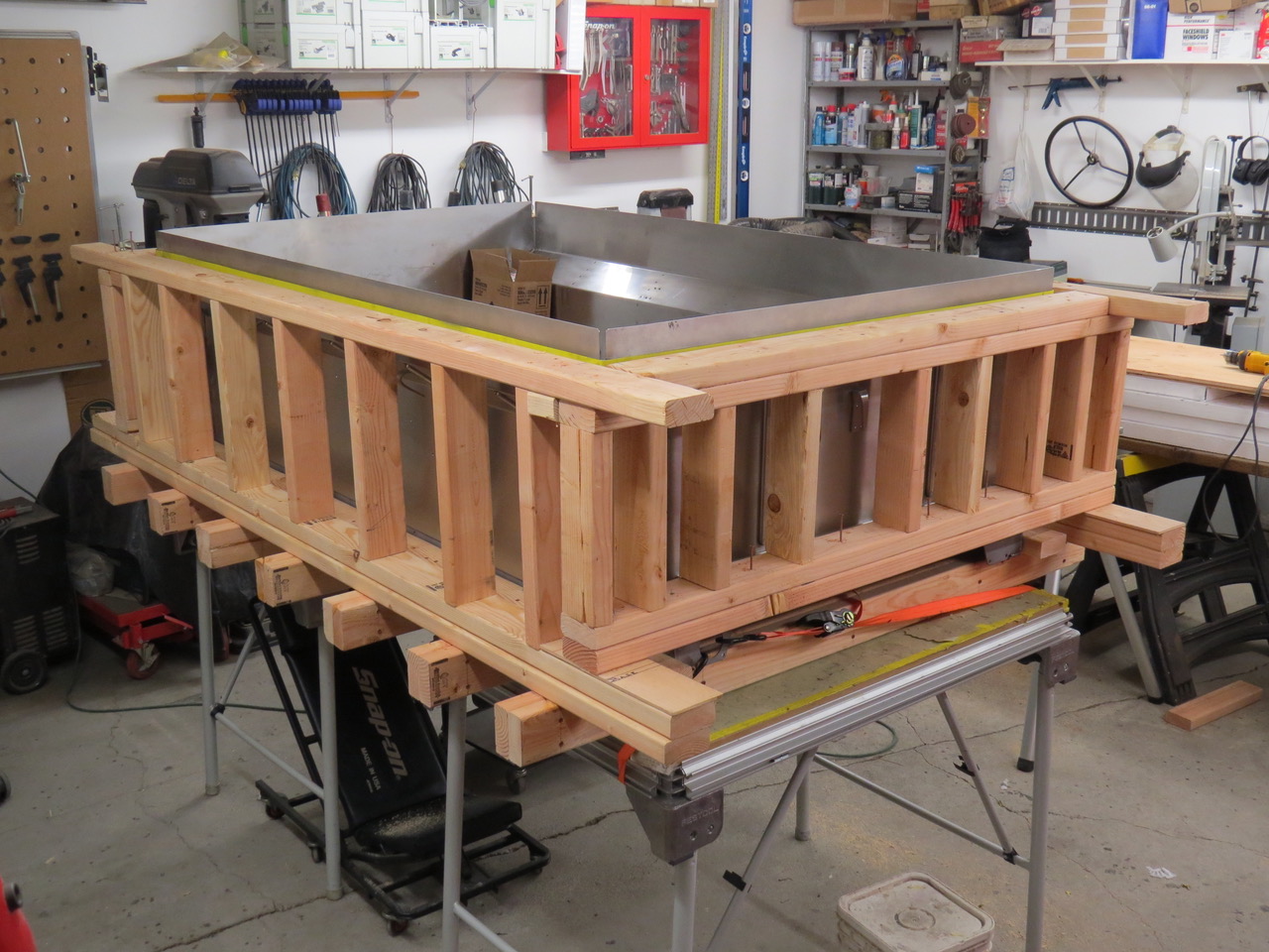
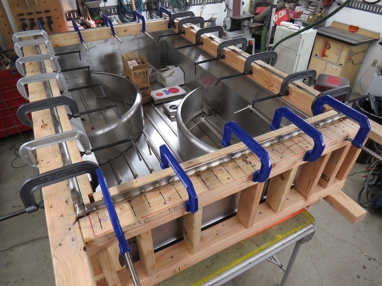
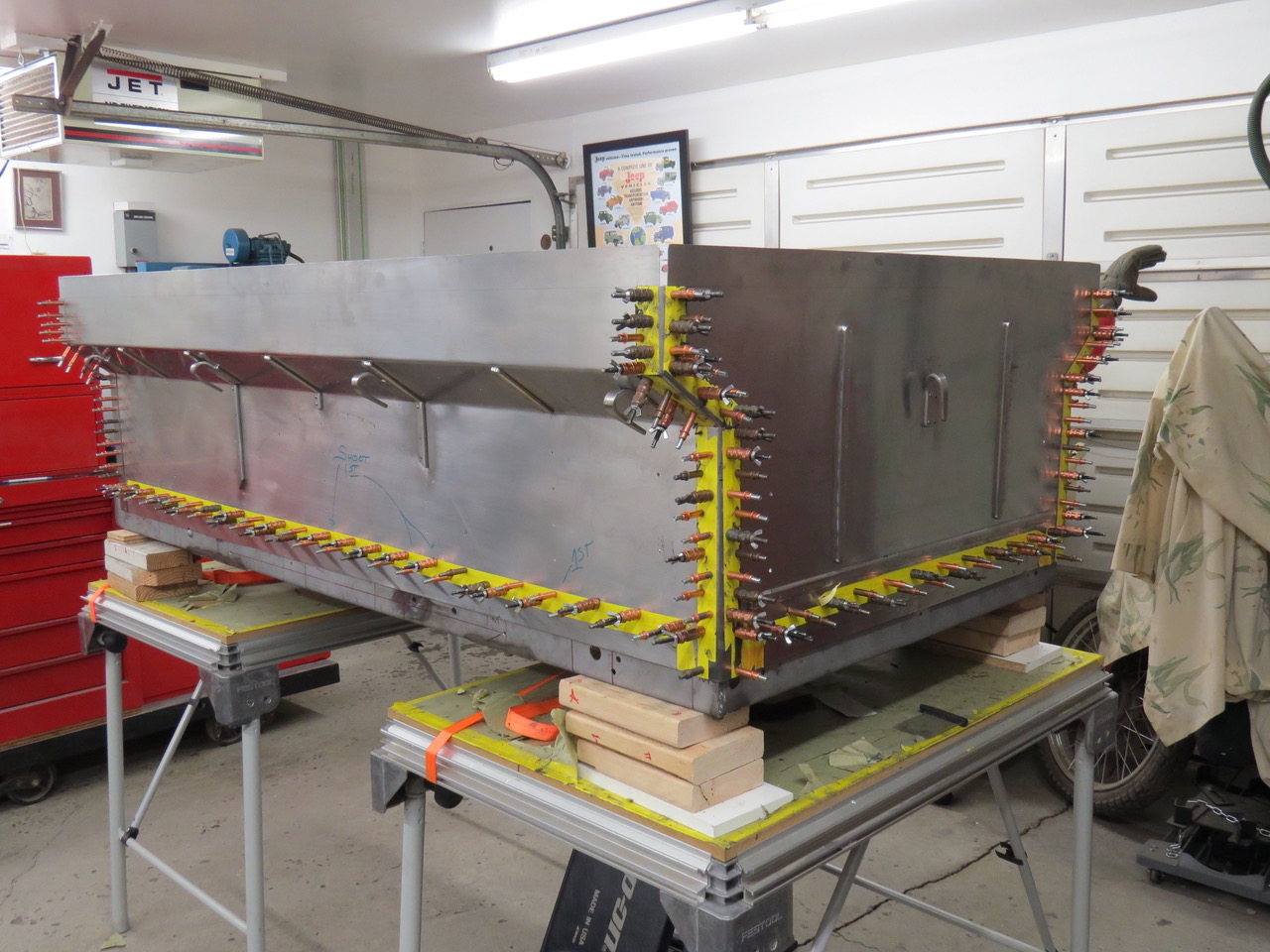
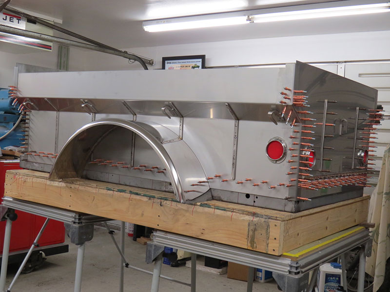
This photo shows the jig I made to keep the trailer box in alignment while I fabricated the upper tube reinforcement and rolled the sheet metal before tack welding the edges.”

2019-02-27-m100-trailer6

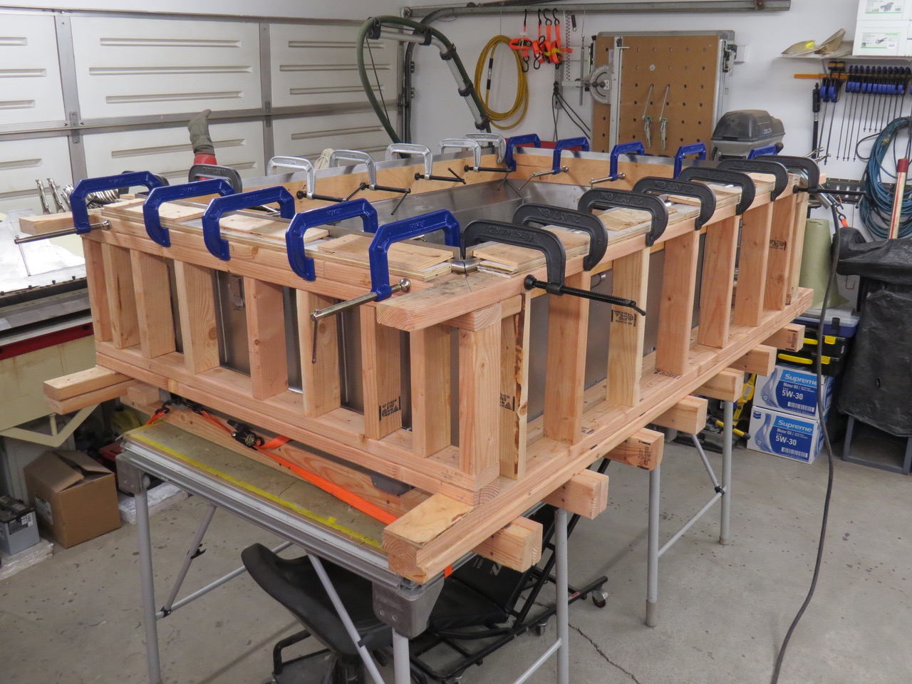
The upper tube has been fitted and held in place with strips of plywood and 24 6 inch C clamps.

2019-02-27-m100-trailer7

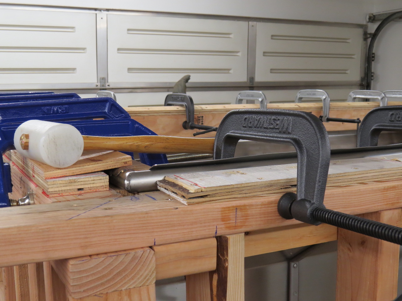
I used a plastic hammer to gently form the sheet metal over the curve of the reinforcing tubing. The C clamps were repositioned often to allow hammer access to the 20 feet of 18 gauge stainless sheet metal around the upper edge of the trailer box.

2019-02-27-m100-trailer8

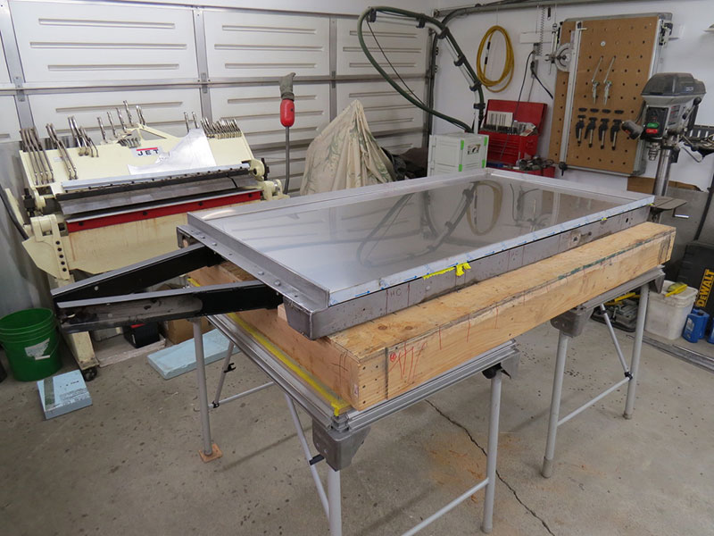
The tack welds are complete so the 2X4 jig can be removed

2019-02-27-m100-trailer9

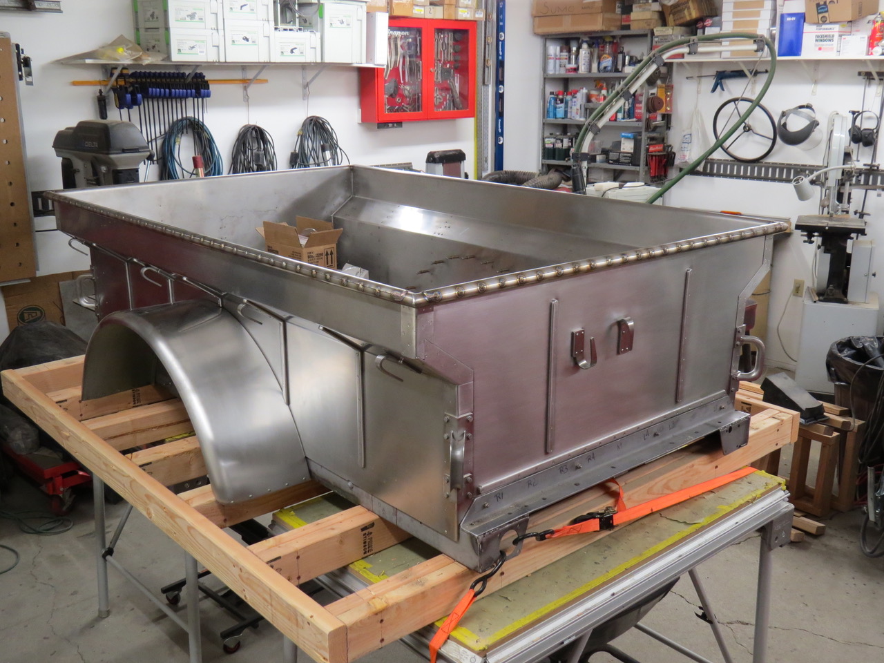
The replacement box is bolted to the original trailer frame and tie down straps hold the frame to the work tables. I had to plan my work around earthquakes.

2019-02-27-m100-trailer10

Continue reading

 
To Top

More Progress on Paul’s Trailer

• CATEGORIES: Features • TAGS: This site contains affiliate links for which I may be compensated.
snow-fall-alaska

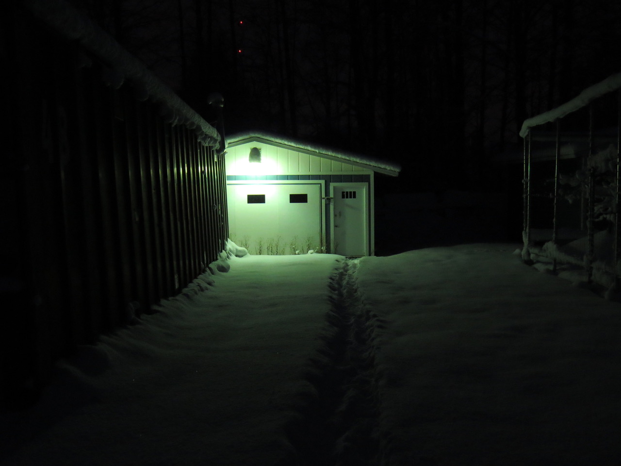
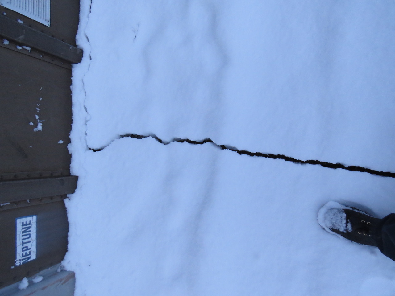
Photo taken at 9am in Anchorage. Still dark out (sunrise was supposed to occur at 10:12 am, but the clouds kept it dark)

As we begin counting longer days, Paul’s toiling away in his warm and cozy garage as the snow falls, the sun hides, and aftershocks rattle Anchorage.

Paul writes, “Since the earthquake November 30th we’ve had almost 5,000 aftershocks in less than three weeks.  Many of the tremors are too light to feel but we’ve had a few strong shakers that concerned me enough to make a trip to the local hardware store necessary where I purchased additional tie down straps.  The trailer and box assembly is still sitting on two work tables and will remain that way until I finish rolling the upper edge of the trailer box.  I’ll rest easier when I get the trailer frame finished, the axle attached and the box lifted off the work tables and bolted to the frame.”

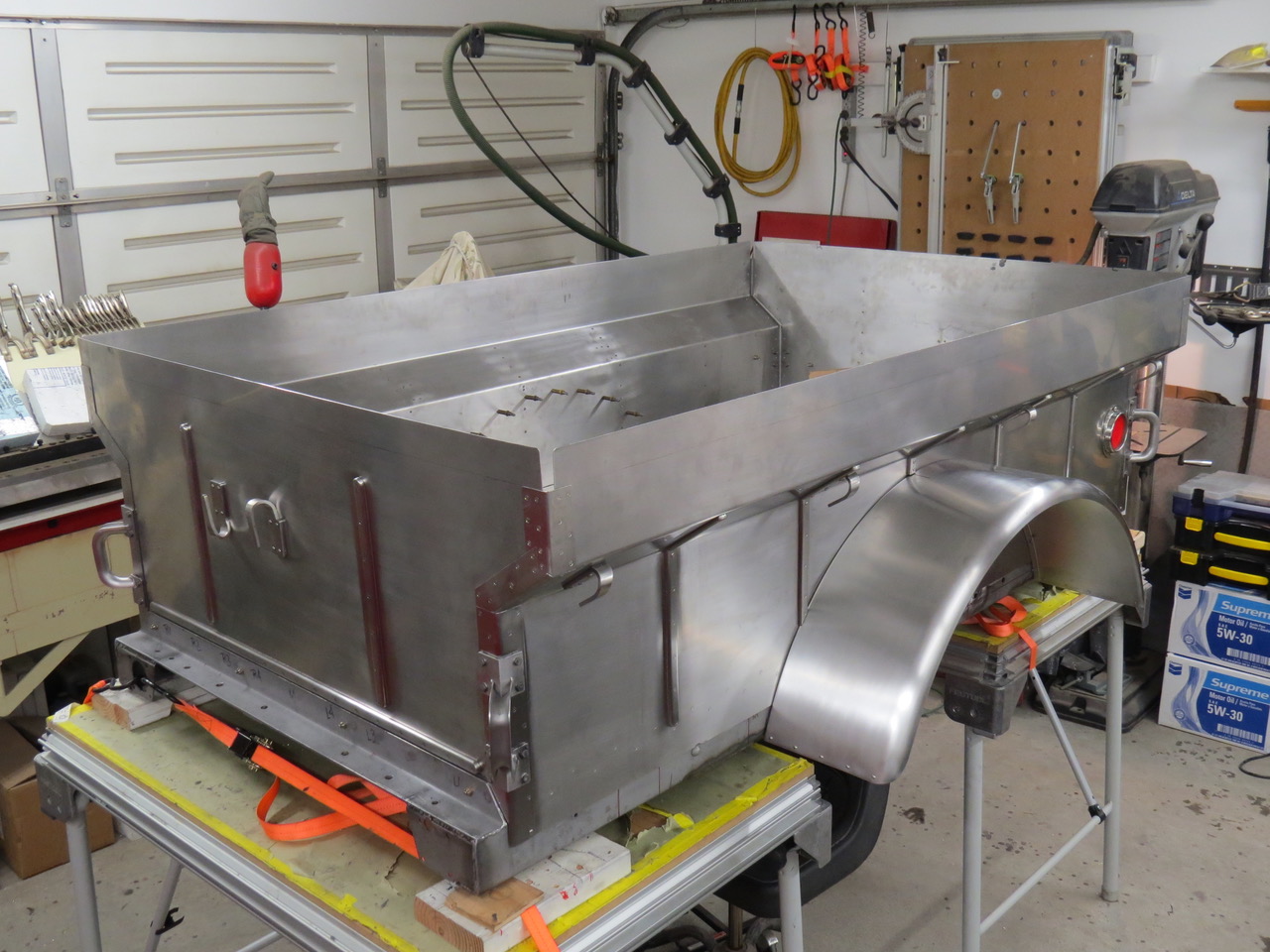
“The trailer box is riveted together so the next step (after the taillights) is to weld the tubing into a big rectangle to match the upper edge of the side panels and then roll the metal over the tubing and weld as necessary.  I’m not quite sure how I’ll accomplish this task but I expect it’s going to cost more than I planned and take longer to accomplish than I’d intended but that’s normal for this project.”

12-20-2018-tail-light-placement-trailer1

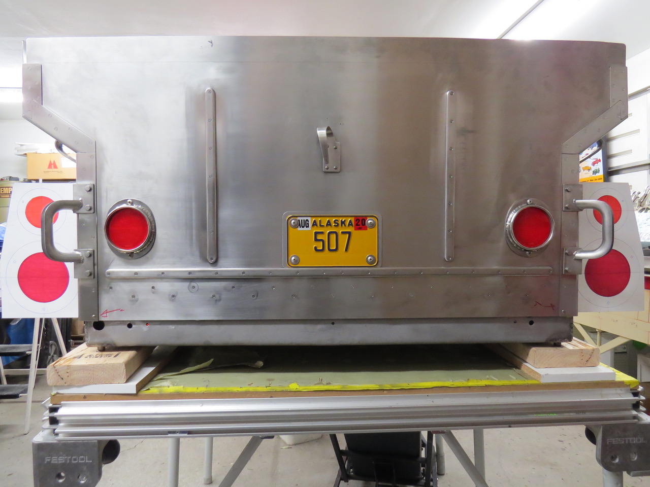
I’ve made 6 or 7 different designs for the taillight/turn signal layout on the M100 trailer but none of them are without problems. Here’s my mockup of the lights mounted to the rear of the trailer. To me they are too close together and would look awkward sticking out from the box.

It would be much easier to position these lights if I went to a smaller size LED light but I want the trailer lights to match the ones I installed on the little Willys so I’m running into location/space issues.

I’ll try again.

12-20-2018-tail-light-placement-trailer4

Here the taillight brackets would be mounted to the trailer sides just forward of the rear corner sections.  They’d be close to but not interfering with the use of the grab handles bolted to the corners.  The housing for the lights would be stainless steel sheet fabricated into a one inch thick box with a removable access panel on the front side.

12-20-2018-tail-light-placement-trailer3

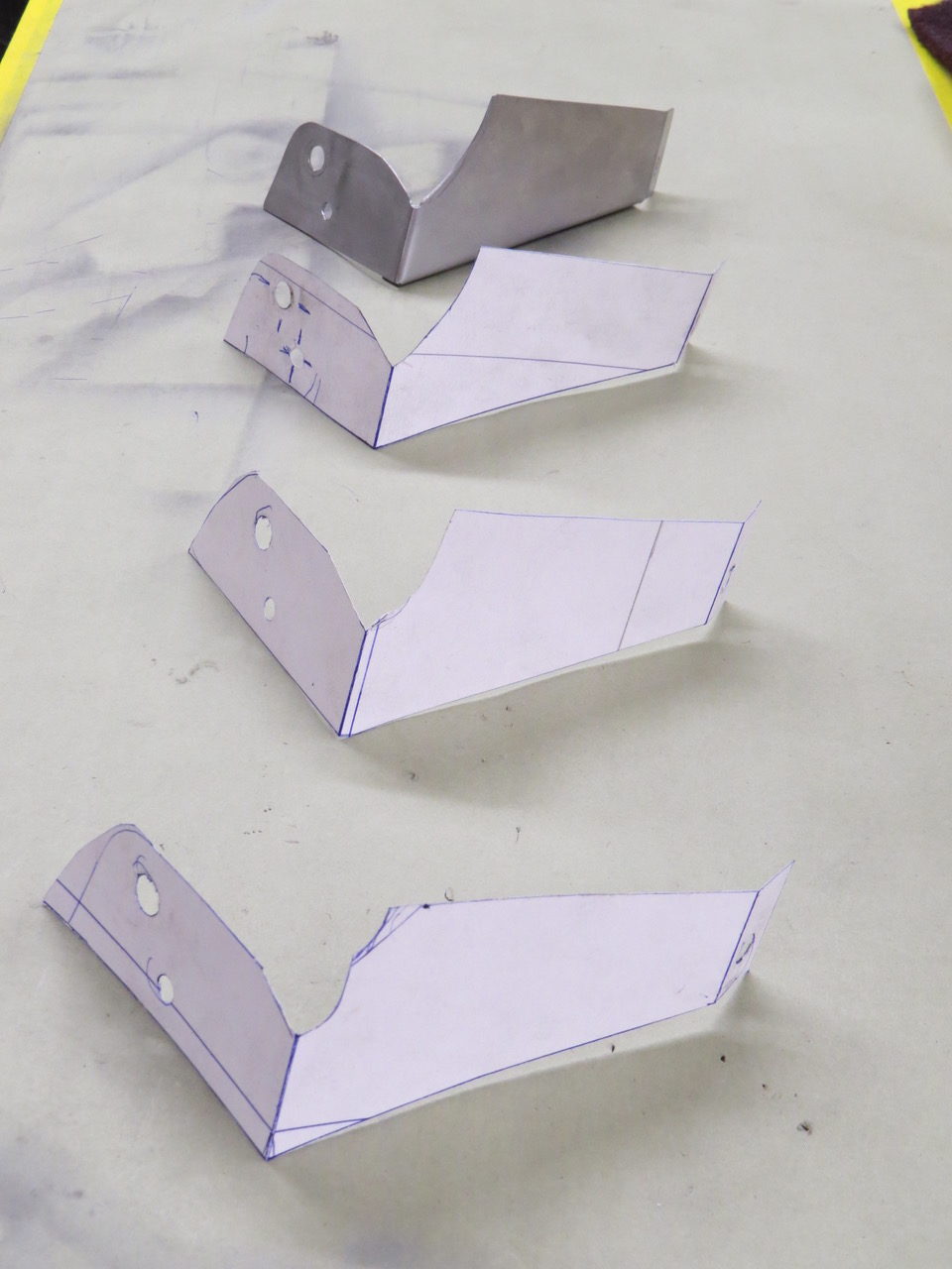
Here are some of the poster board mockups of the tail light housings I’ve made while attempting to achieve a reasonable balance of visibility, secure installation and ease of fabrication.  The first mockups were made from white poster board with line drawings to indicate the light assemblies.  

As I refined my design I began coloring in the tail/brake light lens (red) and the turn signal lens (orange) with felt markers to give me a better idea of how these lights would look on the trailer.  I’m pretty sure I’ll use the mockups number 5 and 6 (starting from the first mockup on the left as #1) as the final design so tomorrow I expect to begin cutting sheet metal.

12-20-2018-tail-light-placement-trailer2

 
To Top

Rock and Rollin’

• CATEGORIES: Features • TAGS: This site contains affiliate links for which I may be compensated.
earthquake4

Paul’s made a little more progress on the trailer.

As you might have heard, Alaska was hit with a good-sized earth quake near Anchorage a couple days ago. Our own Anchorage-based Alaska Paul filed this report:

“This past Monday (Nov 26, 2018) my friend First Larry came over to the house and helped me shoot the 90 remaining rivets in the M100 trailer floor section so I could attach the side panels to the floor flange. The seams where these parts overlap is sealed with a two part rubber like sealant and cleco fasteners hold everything together while the sealant hardens.

Usually the sealant cures within 3 or 4 days so this morning (Nov 30, 2018) I was working in the garage cleaning up the excess sealant by 8am. Because the trailer is sitting on two work tables it’s necessary for me to stand on a 5 gallon bucket which allows me to bend at my waist to clear the trailer sides while still being able to reach the floor panel.

This was the position I was in when Mother Nature decided to remind me just who was really in charge of my life.

We got hit with a sharp jolt and then the garage began dancing. As I was holding onto the trailer rear panel trying to remain upright I noticed the walls of the garage were flexing hard enough to open and close the walk in door and this door had been latched. For some reason the movement of this door fascinated me so I continued watching (while tightly holding onto the trailer) until I realized the door was opening and closing so fast it looked like it was waving goodbye. I agreed it was a good time to say goodbye to the dancing garage so I bounced my way out of the garage and staggered towards the house.

Unlocking the door to the house took longer than usual since my actions resembled a drunk opening a door while on a ship in a storm. A couple of years ago I’d installed outside grab handles on either side off the kitchen door so I hung onto a handle with one hand while I tried to get the key in the lock with my other hand. I gripped the handle so tight I think I left fingerprints pressed into the metal.

After getting the door unlocked I quickly checked on the Goddess (she was fine) and Samson the wonder parrot who was not amused to have his perch catapult him skyward. Samson sought safety on top of his cage in the living room but the many aftershocks continue to irritate him.

In the brief time it’s taken me to write this email we’ve had six noticeable aftershocks along with many little tremors.

While I’ve been thru stronger earthquakes than the ones we had today this main one was impressive. There are reports of power lines down, sections of local roads destroyed, broken water pipes in commercial buildings and traffic signals no longer operational.

The Goddess and I have been real lucky… we never lost electricity, we still have heat, we have enough food to last for more than 3 weeks and since we’re retired we don’t have to go anywhere. We’ll be staying home where we can help the neighbors if need be.

Oh yeah.

The garage made it thru the quake with no damage to speak of, the little blue house shook and shimmied but it’s fine. Some stuff got broken, some stuff got tossed around but the little Willys and the M100 trailer are both fine.

We’re pretty happy

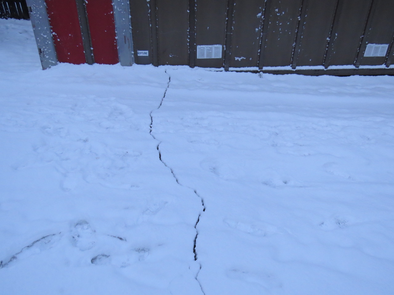
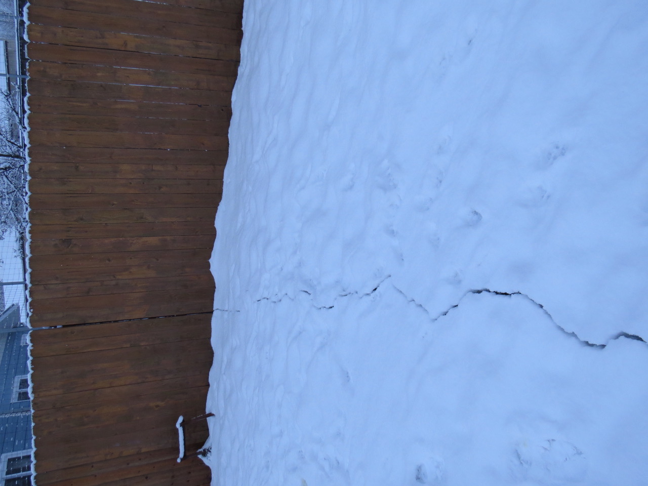
I’ll send a few photos to show the ground cracking in the back yard (See below).

That’s all,

Paul
The Goddess
and Samson the sleeping Wonder Parrot

earthquake2 earthquake1

 
To Top

Paul’s Stainless Trailer Build

• CATEGORIES: Features • TAGS: This site contains affiliate links for which I may be compensated.

paul-stainless-trailer-build11As the days grow shorter in Anchorage, Paul’s getting busy with his trailer. Thanks to Paul for taking the time to document another beautiful build!

“With fall in the air and winter coming fast the first week of September is when I began working on the rebuild of the M100 trailer after I hauled the frame home from the sand blasters. There were a couple of cracks in the frame where the shock mounts attach and a few other areas I felt also needed some attention from the welder so I positioned the frame on a 2X6 and plywood platform and screwed blocks down to hold the frame in alignment. My plan was to fabricate the replacement box on the clean frame and after the box was bonded and riveted together the box would be removed so the frame could return to the powder coat place for a coating off satin black.

paul-stainless-trailer-build3

I felt the original trailer box floor was a little weak so I planned to add extra hat channels for strength and I needed to design and fabricating the tail light, brake light and turn signals mounts.

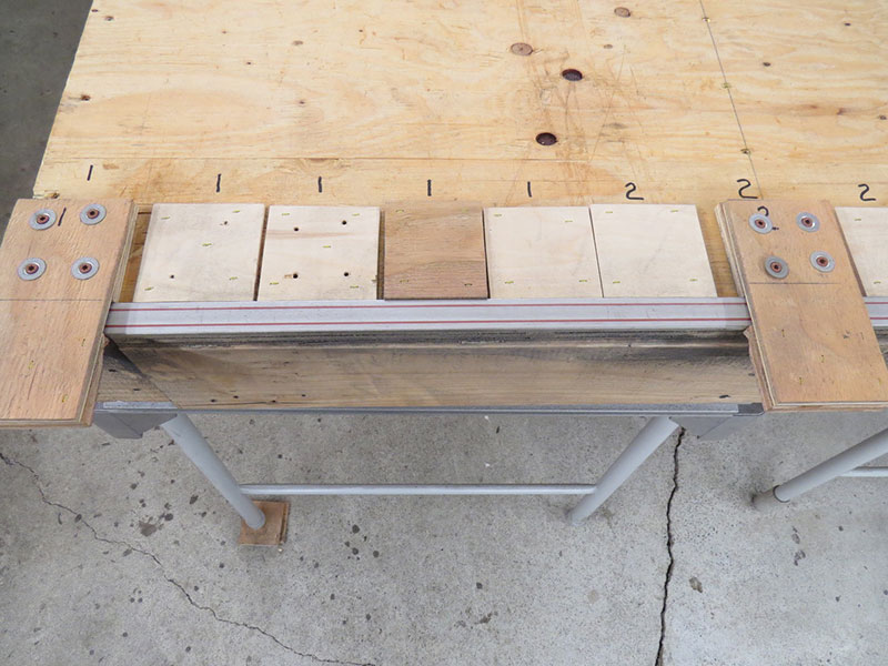
Below is the new 18 gauge stainless steel floor being fitted to the original trailer frame.  I’d hoped to have a local company press the reinforcing strips in this floor panel (like the original) but soon learned I couldn’t afford the cost to make the die and pay for the press time just for one floor panel.  I ended up buying 60 feet of 1 inch wide by 1/4 inch thick stainless steel strap for the trailer floor and 24 feet of 3/4 inch wide by 1/4 inch thick stainless strap for the side and end panel reinforcements.  The strap was rectangular but I needed the floor strips beveled and the side strips rounded along the edges so I had to get creative and come up with a cheap solution to recontour these straps.

paul-stainless-trailer-build4

I used scrap pieces of plywood stapled to the platform along with additional plywood clamps screwed to the wood to hold the strap in position while worked on the strap edge.  By carefully holding a 4 inch grinder at the necessary angle as I rolled from one end of the strap to the other while sitting on a roll around seat I was able to reshape each strap to the contour I needed.  The floor of my garage has a good sized crack down the middle so I had to pay attention and not damage the stainless strap while bouncing across the uneven floor surface.  With my face mask on, my ear protection clamped to my head and nothing much else to do I spent 47 hours grinding theses straps so they would be a reasonable duplicate of the original ridges pressed into the trailer panels.

paul-stainless-trailer-build1

Here’s the end result of rolling back and forth while holding the grinder against the stainless strap. It’s far from perfect but it’s something I can live with.

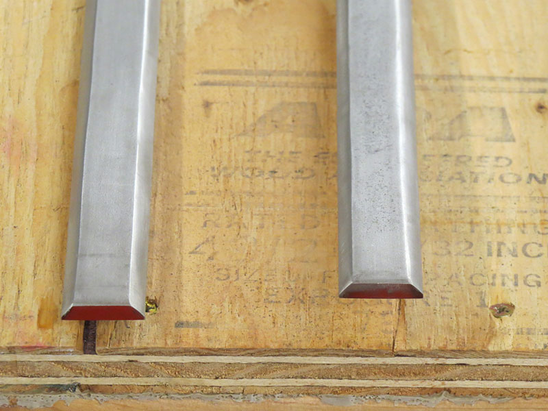
After I’d finished with the sides of the straps I needed to bevel the ends in a 180 degree curve.

paul-stainless-trailer-build12

I miscounted and beveled 10 straps for the floor when I really only needed 9 straps.  Oh well, what’s an extra three hours or so of grinding. Continue reading

 
To Top

Paul’s Mirror Unto His Engine

• CATEGORIES: Features • TAGS: This site contains affiliate links for which I may be compensated.

Paul took advantage of a warm Anchorage day and took this shot showing the reflection of his engine on the hood.

paul-m38-hood-photo

 
To Top

Knardly Rolls Sees the Light of Day

• CATEGORIES: Builds, Features • TAGS: This site contains affiliate links for which I may be compensated.

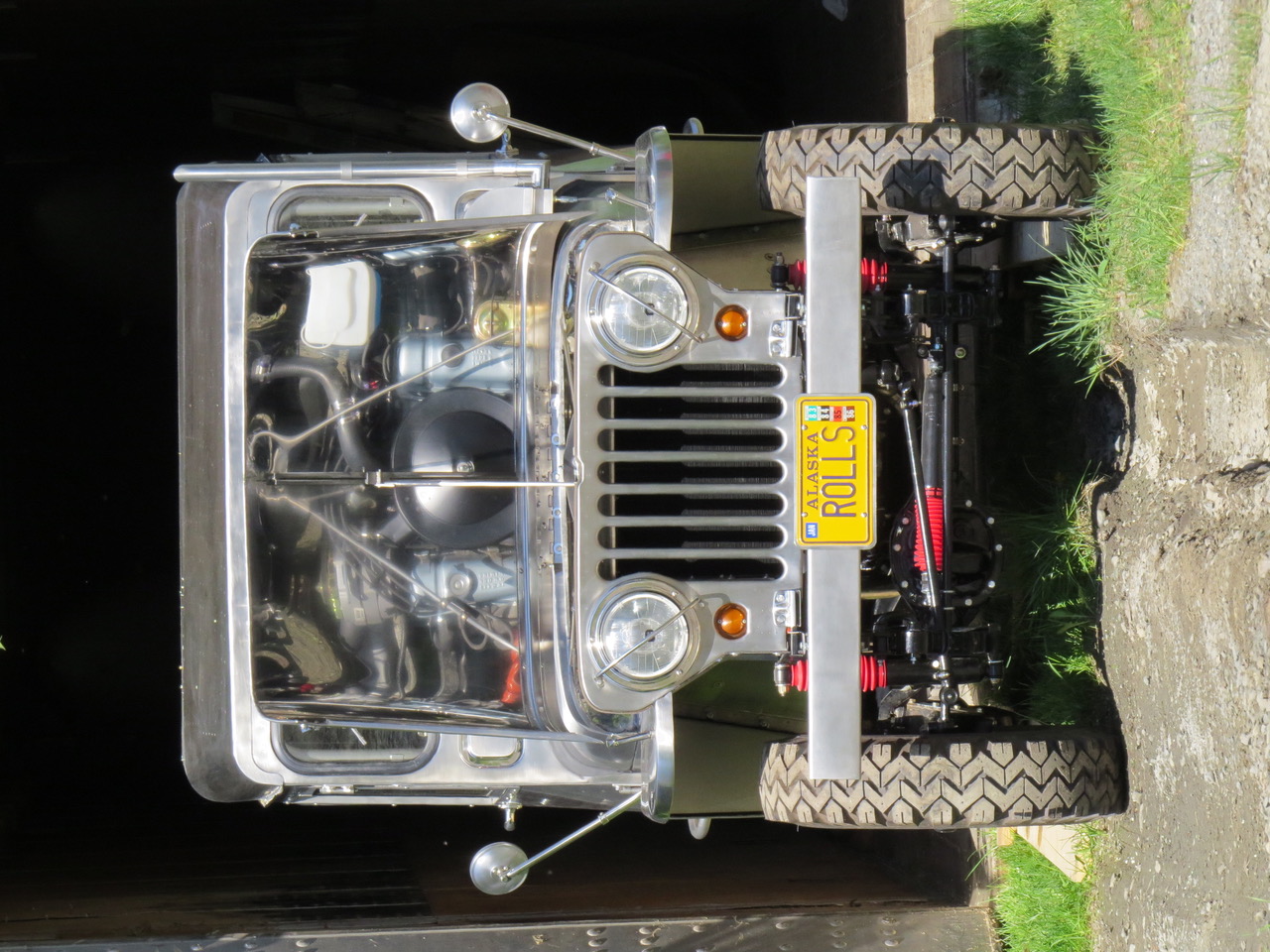
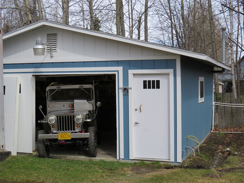
Paul ceremonially rolled Knardly Rolls out of the garage on Monday.

2018-05-07-knarly-rolls0-lores

Knardly Rolls seen peeking out of the garage, wondering if it’s safe.

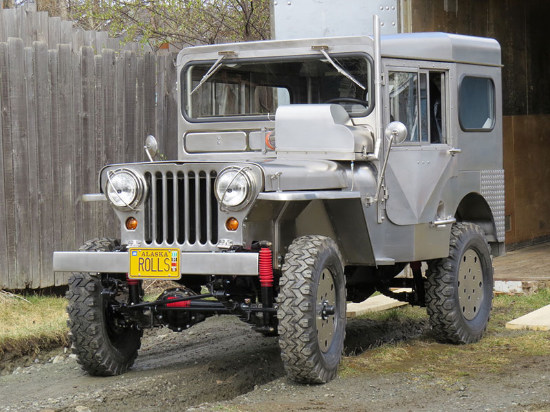
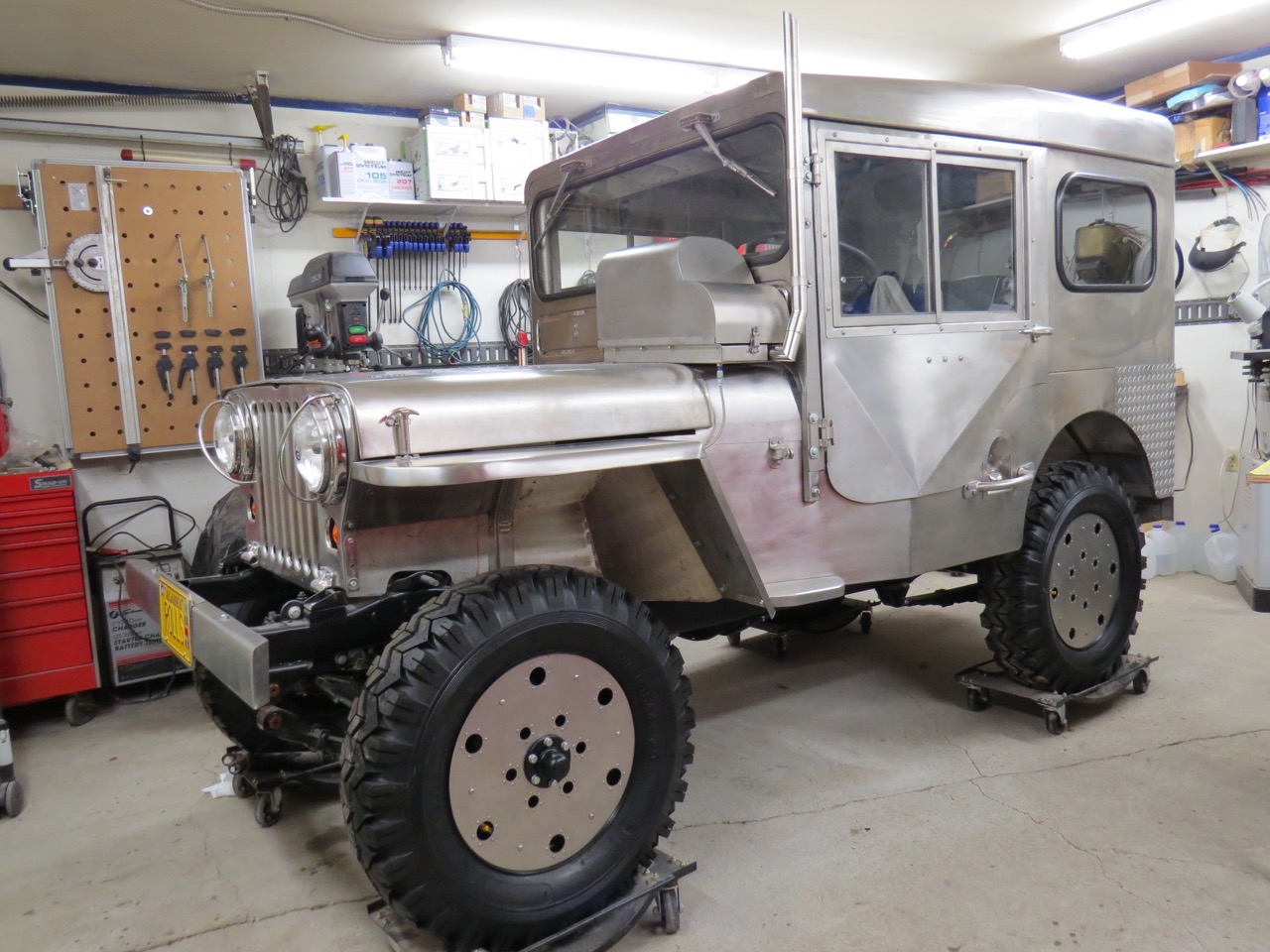
He writes, “Today (May 7th) I opened the garage door and then removed two of the four insulated panels positioned against the outer surface of the garage door so there would be enough room to move the little Willys from the dark garage and into the May sunshine. I quickly learned I need sun glasses. Most of the body has a brushed pattern on the stainless steel but even brushed stainless is rather reflective when the sun is shining. I’m real glad I didn’t polish the body, that would have been blinding on a sunny day.

The little Willys has been moved into the connex where I’ll fuel it up, check for leaks and see if the engine will start. Once the engine runs well I’ll support the Willys with jack stands and begin testing the operation of the transmission and axles.

2018-05-07-knarly-rolls1-lores

However, before I begin any ground running I’m going to repaint the interior of the garage. The last time I painted the garage was 30 years ago so new paint is long overdue.

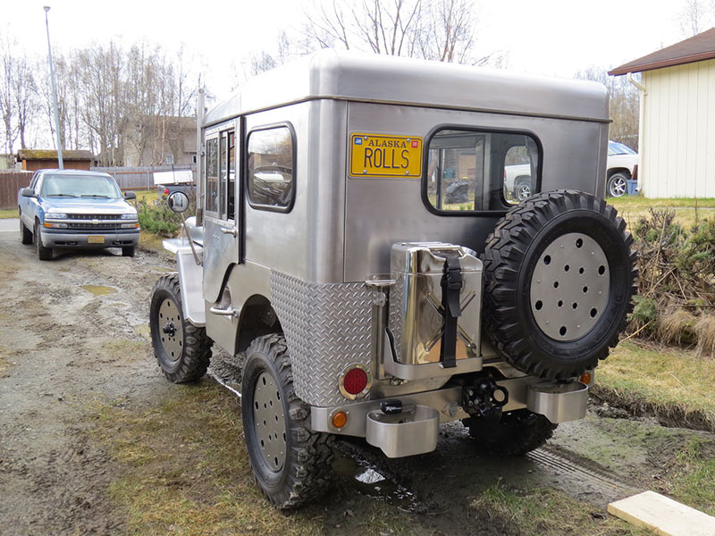
Anyway, here’s a photo of the little Willys escaping from the garage. It was a whole different perspective for me since the small garage only allowed me close up views but once it was outdoors I was able to back away and get a view of the entire Jeep. Quite different from what I’m used to.

I’m still having a hard time believing the little Willys is finally done but seeing it outdoors makes it seem more real.”

2018-05-07-knarly-rolls2-lores

 
To Top

Knardly Rolls Rolls for Reals, 32 Years Later ….

• CATEGORIES: Builds, Features • TAGS: This site contains affiliate links for which I may be compensated.

Well, he did it. A big CONGRATULATIONS TO ALASKA Paul. He installed the final part onto his stainless 1952 M-38 Knardly Rolls on May 2nd, 2018. I, for one, look forward to hearing about the inaugural run!

From: lemonade

To this 32 years and 5 months later: paul-m38-1

Here’s what Paul wrote,

“Somehow, despite my best efforts, I finally managed to complete the never ending rebuild of the little stainless steel Willys. The last part (the rear driveshaft) was bolted to the axle at 12:30 pm today, May 2nd 2018 ending a multi decade effort that began when I dropped the engine off at the rebuilders on December 2nd 1985. Over the years I’ve used the date the stainless steel body was ordered as the project start date but that happened over a month after the engine went to the rebuilders.

From the starting date to the completion date this project took 32 years and 5 months of time. I realize I’m slow but I never expected I’d take over three decades to rebuild one Willys Jeep …… it’s good I don’t do this for a living. I’m glad I finished it while I’m still flexible enough to climb into the driver’s seat, the Goddess suggested I make a stainless steel walker because I might need one before I finished the little Willys. She’s helpful that way.

The backyard is quite soggy so I’ll have to wait a week or so before I can reposition the Willys from the garage to the connex for leak checks and static runs. If things go well I hope to be cruising thru the neighborhood by late May.

Naturally, the garage must be filled with a project before winter so this fall I’ll move the remains of the 1951 M100 trailer inside where I’ll begin to fabricate a stainless steel box on the original frame.

Other than that the Goddess and I are having fun under the midnight sun here in the northland. By mid May the trees should have leaves, the night time temperature should stay above freezing and we shouldn’t have anymore snowfall until late September.”

 
To Top

More From Paul

• CATEGORIES: Builds, Features • TAGS: This site contains affiliate links for which I may be compensated.

Paul shared a couple of other recent milestones on his Willys journey.

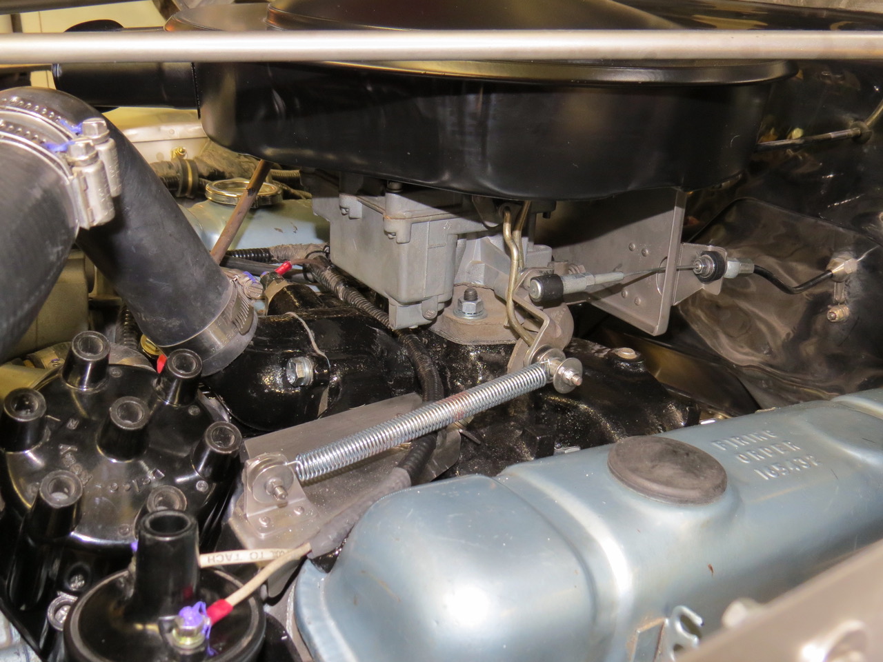
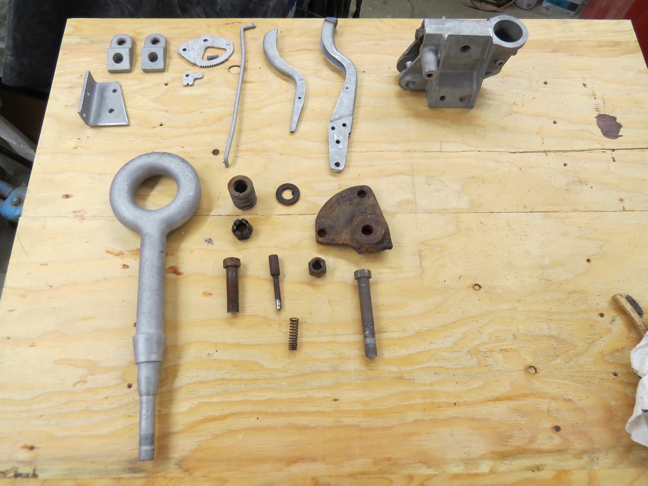
1. The Throttle Spring:
After hooking up the throttle linkage to the carb  (a cable system) I realized not only was I missing a throttle return spring but I was also missing a throttle return spring attach point.  A trip to the local auto parts store provided me with a selection of different throttle return springs but I was on my own when it came to the spring attach point.  More poster paper was sacrificed to make three patterns before I came up with a return spring attach bracket I liked and that would fit without getting in the way of the distributer cap.  I made the return spring attach bracket from stainless steel and incorporated a fastener to allow a coil wire clamp to be bolted to the bracket.

2017-12-31-throttle1

Here’s the cable throttle linkage, the throttle return spring, the return spring attach bracket and the clamp for the coil wires.  The red on the return spring is dried blood …. I managed to poke myself quite a few times while attempting to curl the spring ends to match the attach brackets and those springs are sharp.  Oh well, some folks pay people to poke them with needles and call it acupuncture.  All I have to do is go out to the garage and work on the little Willys, there’s always some sharp edged stainless part waiting to cut me before I even realize it.  That metal can be mean sometimes.

2017-12-31-throttle2

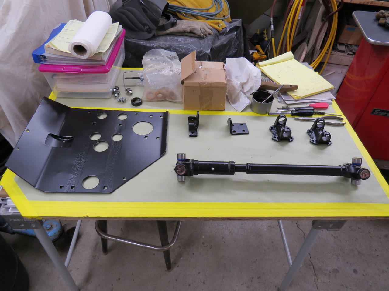
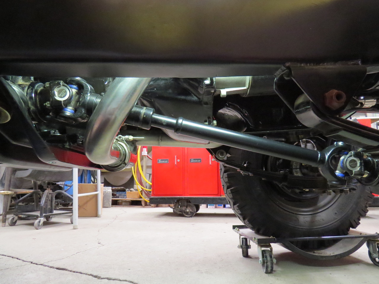
2. The Front Drive Shaft:
The position of the V6 engine made the original front driveshaft too long and the rear driveshaft too short but right now I’m concentrating on the front driveshaft only. I bead blasted the front driveshaft, took the necessary measurements between the transfer case outlet and the front axle attach point and it was time to visit with the local driveshaft guys. After cutting the driveshaft to the correct length it was welded back together, new universal joints installed and then balanced before returning to me. I removed the new u joints, did a quick bead blast cleanup (after removing all traces of the really sticky grease on the splines) and dropped it off to have it powder coated.

The next day the driveshaft was ready to come home so I could reinstall the new universal joints and then bolt this thing on the little Willys. The last time this driveshaft was installed on the little Willys was when it did it’s major meltdown in October of 1985. Wow, I’ve been waiting over 32 years to reinstall this driveshaft. It doesn’t seem it’s been that long but the color (or lack of it) or my hair tells me more than a few decades have gone by. I remember when I was still in my 30’s my hair was brown, not Arctic Blonde (White) like it is now.

Oh well, as much as I tried to take my time installing the driveshaft the four u bolts were quickly tightened and torqued and it was time to find the next to do item on the little Willys.

2017-12-31-driveline1

The front driveshaft is installed on the little Willys for the first time in over 32 years. WOW!

2017-12-31-driveline2

That’s all, Paul
P.S. Happy New Year!
 
To Top

Paul’s Deflecting the Heat

• CATEGORIES: Builds, Features • TAGS: This site contains affiliate links for which I may be compensated.

Paul shared this update on some custom heat shields for Knardly Rolls.

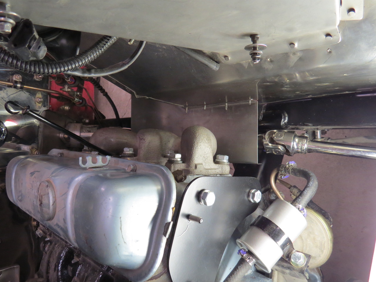
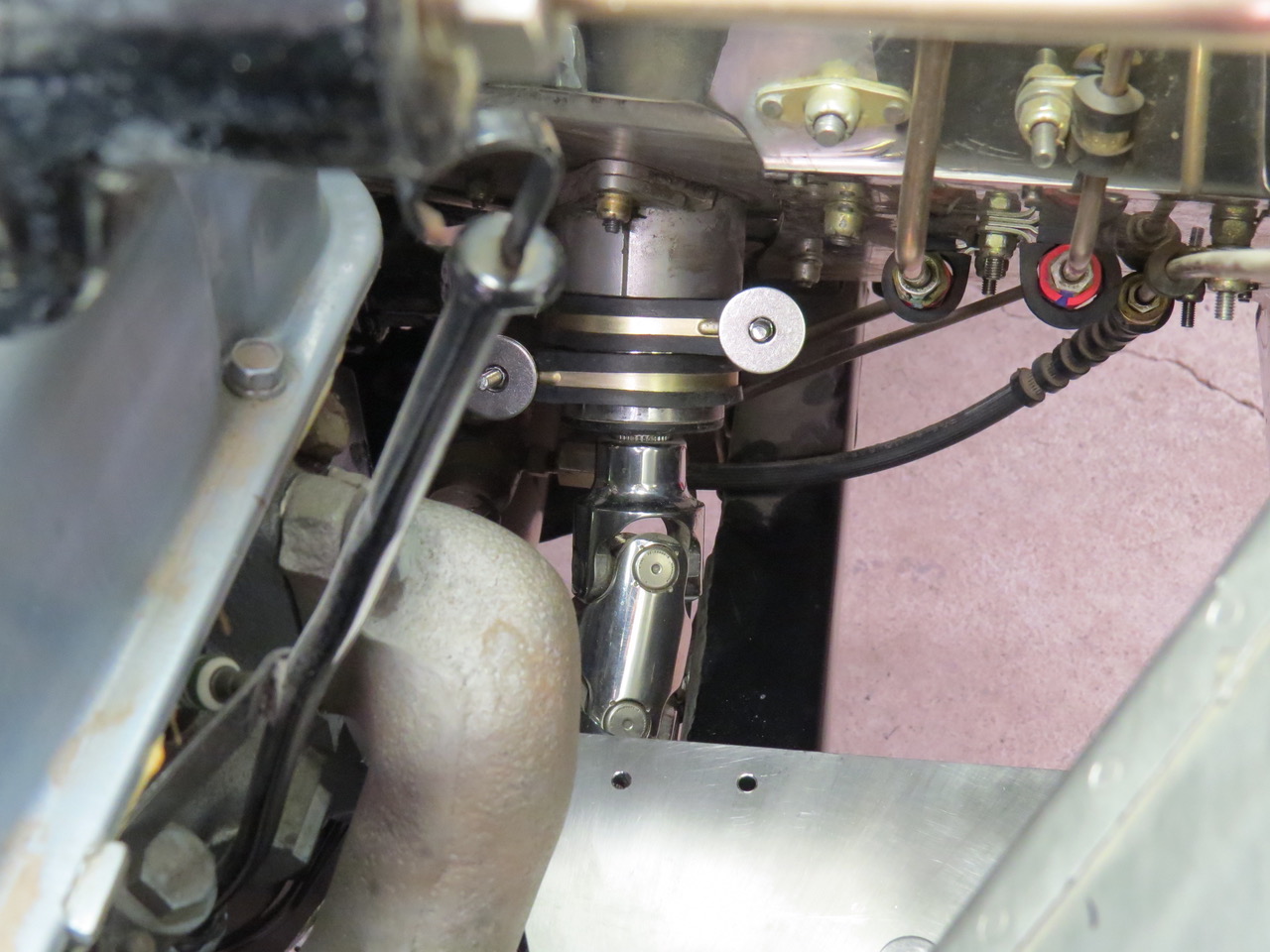
Paul writes, “The exhaust manifold is closer to the steering linkage than I’d originally intended but there isn’t any easy way to increase the distance between these two systems so I decided the best solution to this problem was to make some stainless steel heat shields that would bolt to the fender and fit between the exhaust manifold and the steering linkage.  

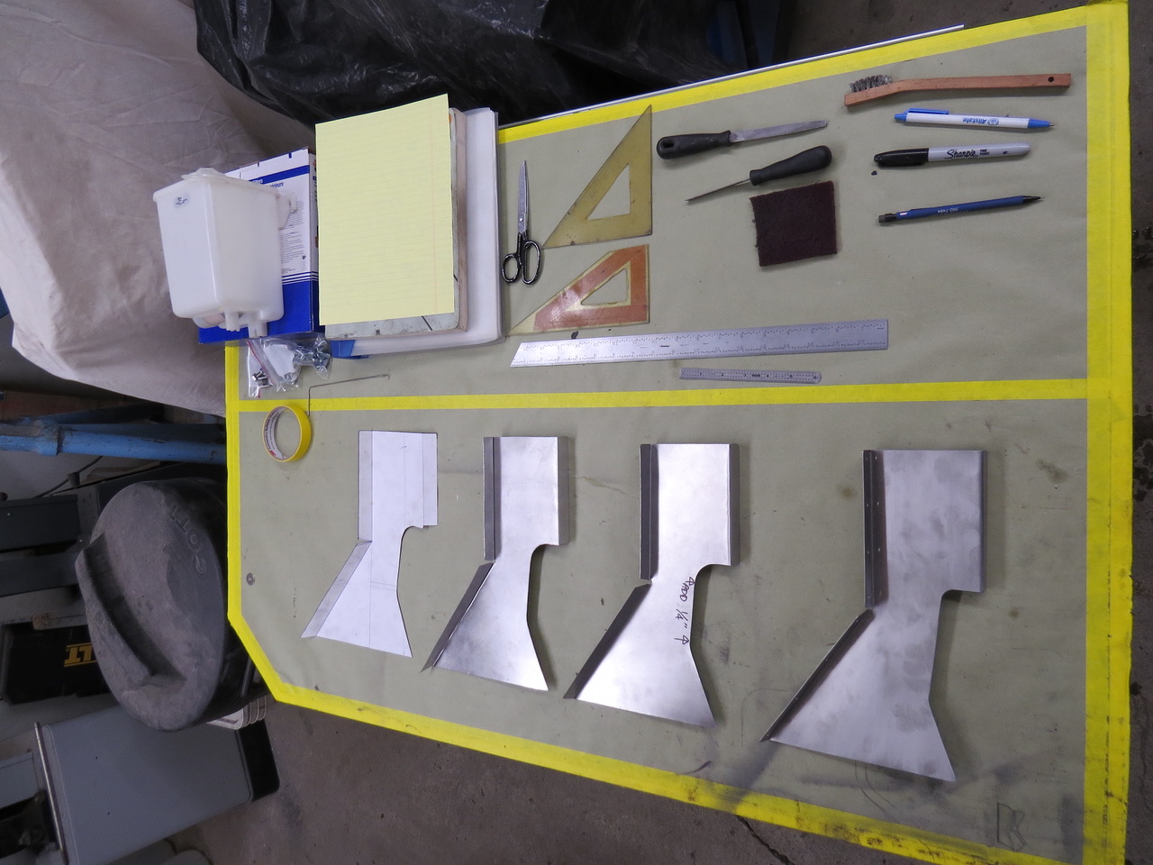
First I quickly made a test shield from some leftover poster board so I could check how this paper part would fit before I cut any stainless sheet.  Once I had the shape of the heat shield figured out I made a test piece from thin gauge aluminum.”

2017-12-31-heat-shields2

“First I made a test heat shield from poster board to check for the correct shape.  Once I was satisfied with the shape of the heat shield I made one from thin aluminum to double check any clearance issues.  After the aluminum shield was modified I made a third shield from thin stainless sheet but I saw a need to fit the fourth and final heat shield a little closer to the manifold and also use a thicker gauge of stainless to prevent unwanted flexing during use.  Once the fourth shield was fitted I drilled the attach holes and bolted the shield to the front fender.”

2017-12-31-heat-shields3

“Here’s the final heat shield temporarily attached to the front fender using Clecos so I could drill the fender and the heat shield at the same time.”
2017-12-31-heat-shields4

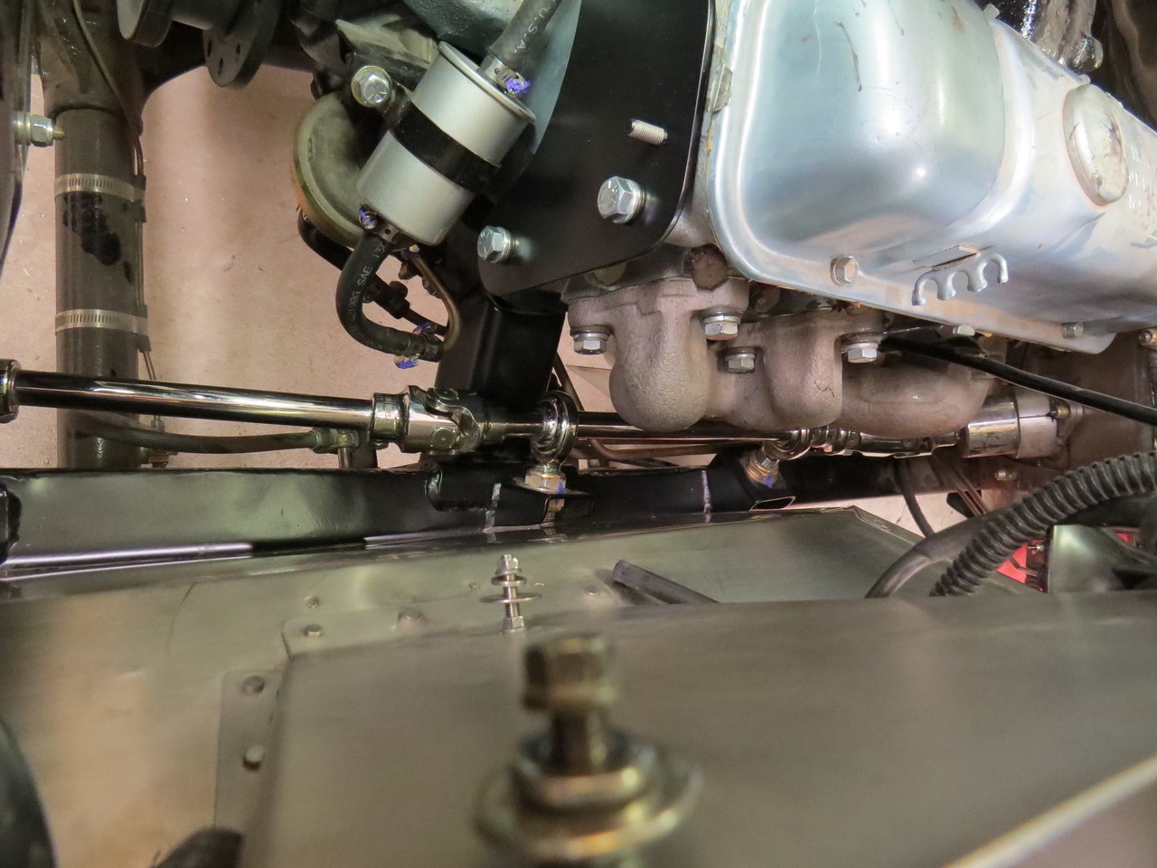
“As you can see, the double U joint between the lower end of the steering column and the first steering shaft is still exposed to heat from the exhaust manifold so another heat shield was necessary.  This smaller heat shield will be attached to the steering column by adel clamps so it’s easily removed for maintenance.  The two adel clamps are bolted to the column with enough threads exposed on the fasteners to attach the aft end of the second heat shield while the forward end of the second shield attaches to the aft end of the first heat shield where the two empty holes can be seen.  If you read that last sentence fast it sounds like a square dance call.”

2017-12-31-heat-shields5

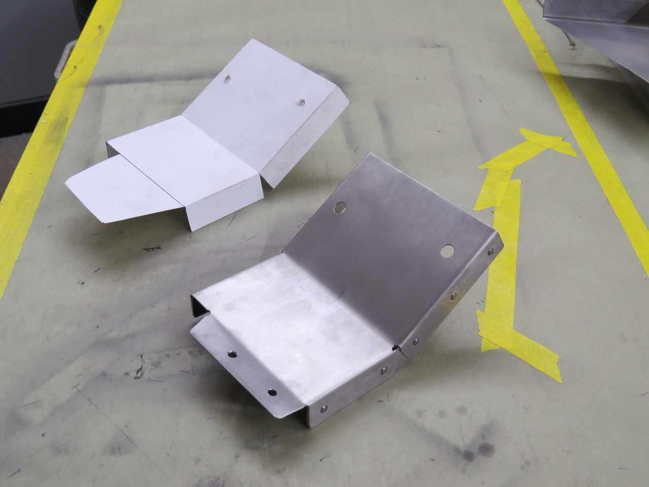
“Here’s the paper pattern and the finished stainless steel second heat shield ready for installation.”

2017-12-31-heat-shields6

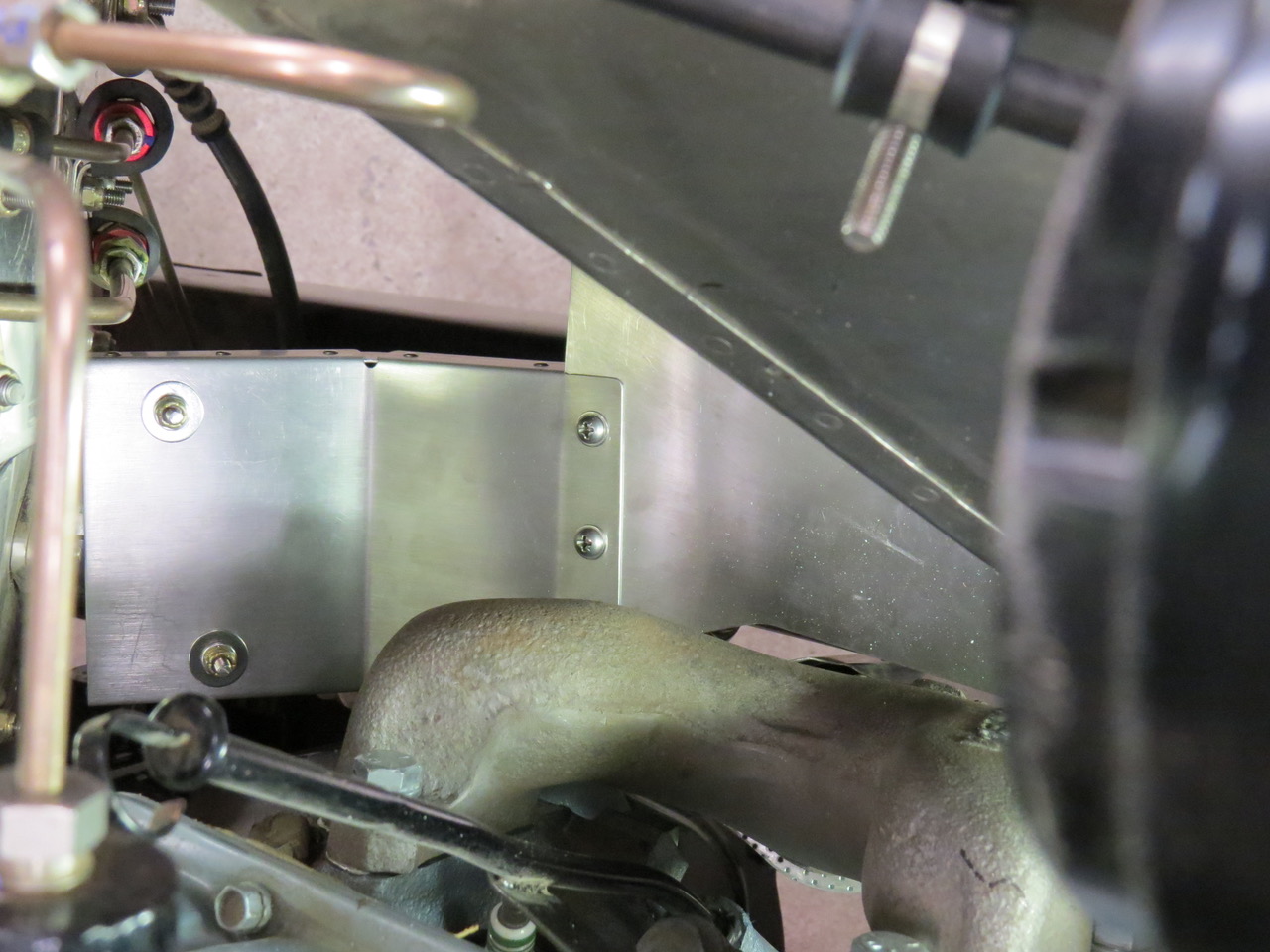
“With the second heat shield installed I think most of the exhaust manifold heat will be deflected away from the steering linkage thus preventing damage to the U joints and shafts.”

2017-12-31-heat-shields7
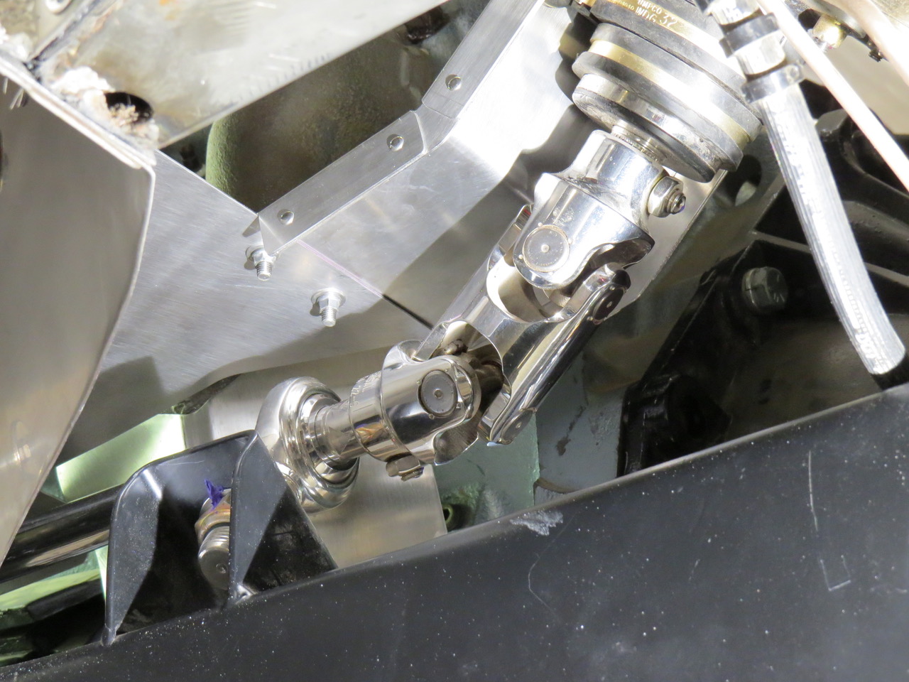
“An underside view shows the clearance between the steering linkage and the heat shields”
2017-12-31-heat-shields8

 
To Top

Alaska Paul’s Placard Progress

• CATEGORIES: Builds, Features • TAGS: This site contains affiliate links for which I may be compensated.

Today’s the last day of the year, so let’s go out in style with Alaska Paul’s placard progress. Paul understands that his one-of-a-kind electrically and mechanically designed jeep will require information assistance just in case any of us lesser mortals attempt to drive it. So, he spend some time over the holidays playing with placards.

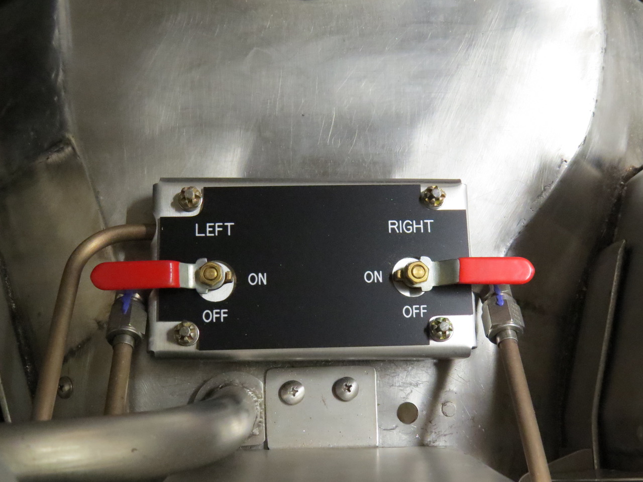
Paul writes, “It’s been a while, so I figured I’d send some Willys progress photos your way. This photo is of the fuel valves between the front seats with an engraved placard sitting on the metal cover. A local sign shop (Alaska Laminated Signs) made up some test placards so I could see how different colors would look with the stainless, gray and blue interior of the Willys.  While this placard has all the necessary information and the correct shape to fit the metal cover plate I wasn’t too happy with the black background and the white lettering.  I wanted something with more visual appeal so Dave (the sign shop owner) duplicated this placard using a brushed aluminum outer layer over a black base.(see next pic)”

2017-12-31-placards2
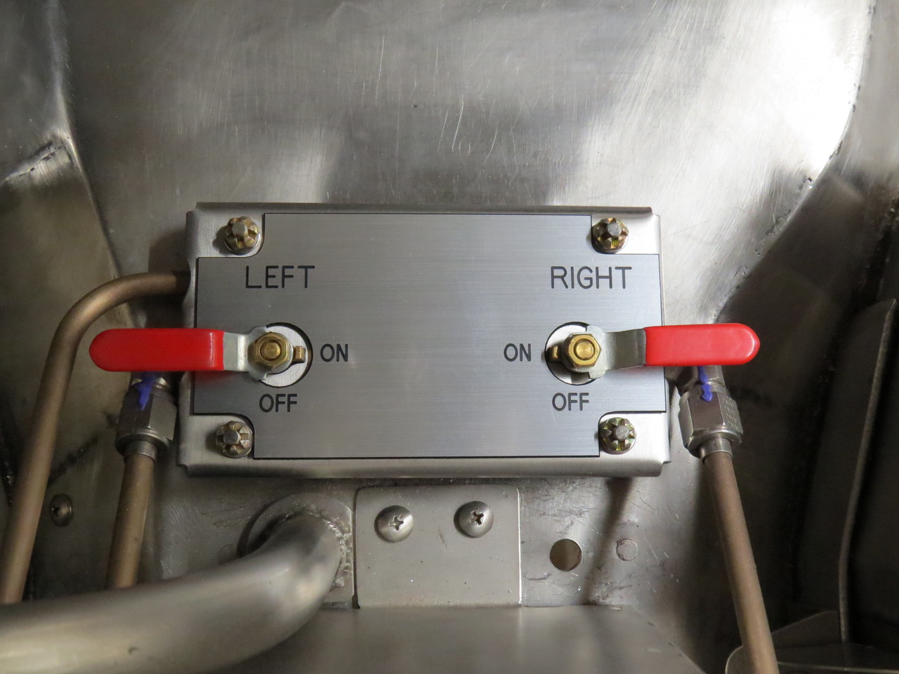
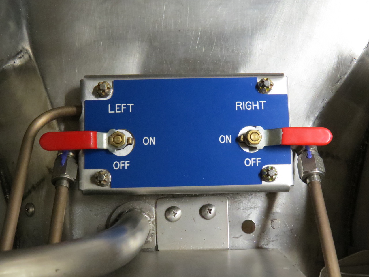
“This aluminum/black combination looks good by itself but I didn’t feel it looked good when it was placed next to the stainless steel parts so Dave made a third placard using a dark blue upper layer and a white base (see next pic).”
2017-12-31-placards3
“Now this is what I was looking for.  While the blue on the placard isn’t a perfect match to the blue on the seats they’re close enough so they look good together and the contrast between the white letters and the blue background makes it bright and easy to see.  Now that we had a color selected I gave Dave my metal full size patterns for the five placards needed for the little Willys and he began the cutting and engraving process.”
2017-12-31-placards4
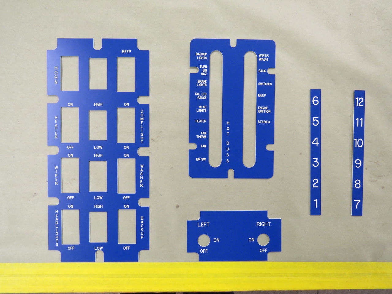
“Here’s the finished product. From left to right we have the overhead switch placard, the circuit breaker placard and below that is the fuel tank selector placard and the final two placards are for the 12 Bosch relays (two rows of six each) in the electrical bay just aft of the passenger seat.

The placards fit perfectly which made installing them a fast and simple task.”
2017-12-31-placards5

“The electrical bay with the placards installed.  It’s hard to see but just below the row of number 1 thru 6 relays is another row of 7 thru 12 relays but not all are in use right now.  I wired in some extra relays and extra circuit breakers incase someone wanted to install additional electrical equipment in the future.” Continue reading

 
To Top

Paul’s Trailer Update

• CATEGORIES: Builds, Features • TAGS: This site contains affiliate links for which I may be compensated.

Paul’s continuing to make progress on his trailer.

I can’t remember if I explained about the lunette thread damage and what it took to get it repaired so here’s the brief story. Before I began disassembly of my M100 trailer I liberally sprayed all the fasteners with penetrating oil numerous times in hopes of easing the removal process. Most of the nuts and bolts unscrewed with normal effort (including the castle nut on the lunette) but I was disappointed to see some of the threads on the lunette were damaged by the nut when things came apart.

Once the lunette was cleaned and bead blasted I took it to a local machine shop to see what could be done to repair or replace the damaged threads. Because I didn’t know if the lunette was cast or forged the machinist said welding was out of the question and suggested I just buy a replacement lunette. I returned home and made numerous phone calls to military parts sellers, Jeep parts sellers and anyone else I thought might possibly have an M100 lunette for sale. Not only did I come up with a big fat nothing for a replacement lunette I also learned these things are harder to find than unicorns. I made a trip back to the machine shop and had another conversation with the talented folks about the lack of replacement lunettes before we brainstormed about the possibility of thread repairs.

After I answered all their questions about the M100 trailer weight, load capacity and the type of use it will be subjected to a solution was suggested. The plan was to carefully remove the damaged threads and then cut new threads on the slightly smaller diameter of the lunette. The thread pitch would be an uncommon type so they would have to make a castle nut of the correct diameter with matching threads but very little strength would be lost with this repair. I wanted one change made with their repair plan, instead of making one castle nut I wanted them to make four nuts. That way if I ever lost or damaged a special nut I’d have spare nuts on hand.

The attached photo shows the thread damage on the lunette, the focus is poor but the missing threads are still visible.

paul-lunette-repair

Continue reading

 
To Top

Paul’s Trailer Restoration Continues

• CATEGORIES: Features • TAGS: This site contains affiliate links for which I may be compensated.

Paul’s made more progress on his M-100 trailer restoration/transformation into stainless steel.

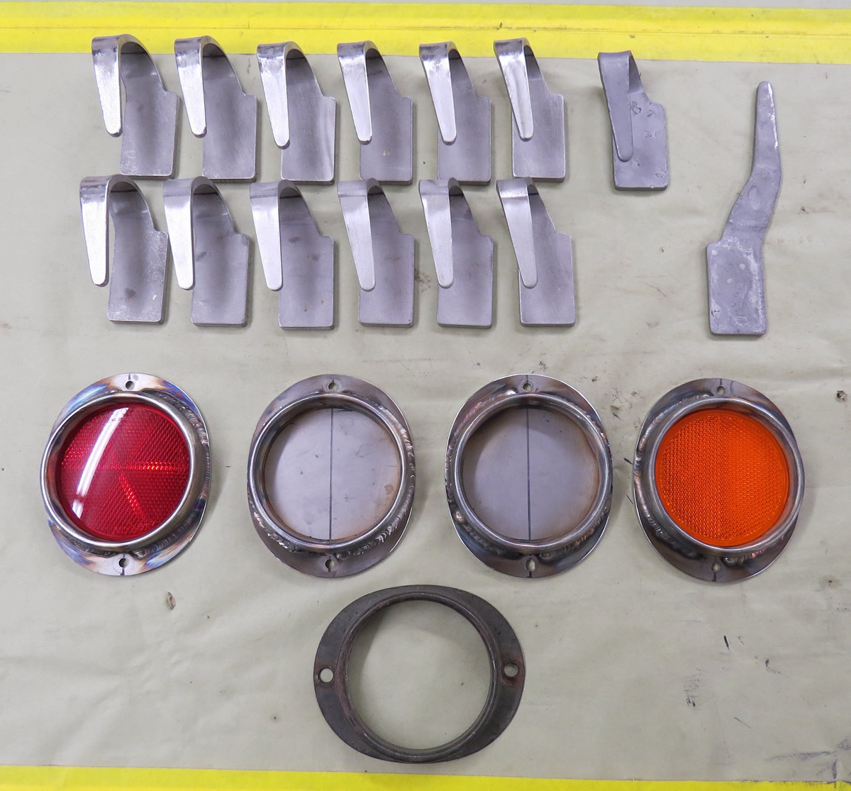
He wrote, Twelve cut and bent stainless steel tie downs for the M100 trailer with two original tie downs (one has been straightened) along with four replacement stainless reflector bodies just above an original reflector body.

stailness-steel-tie-downs2

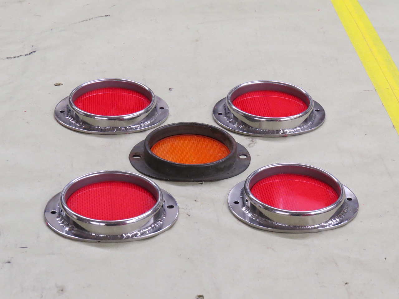
The old reflector and the new replacement reflectors. The replacement tie down hooks and the reflectors will join the other repaired or fabricated parts in the crawlspace under the house until needed.

IMG_5144

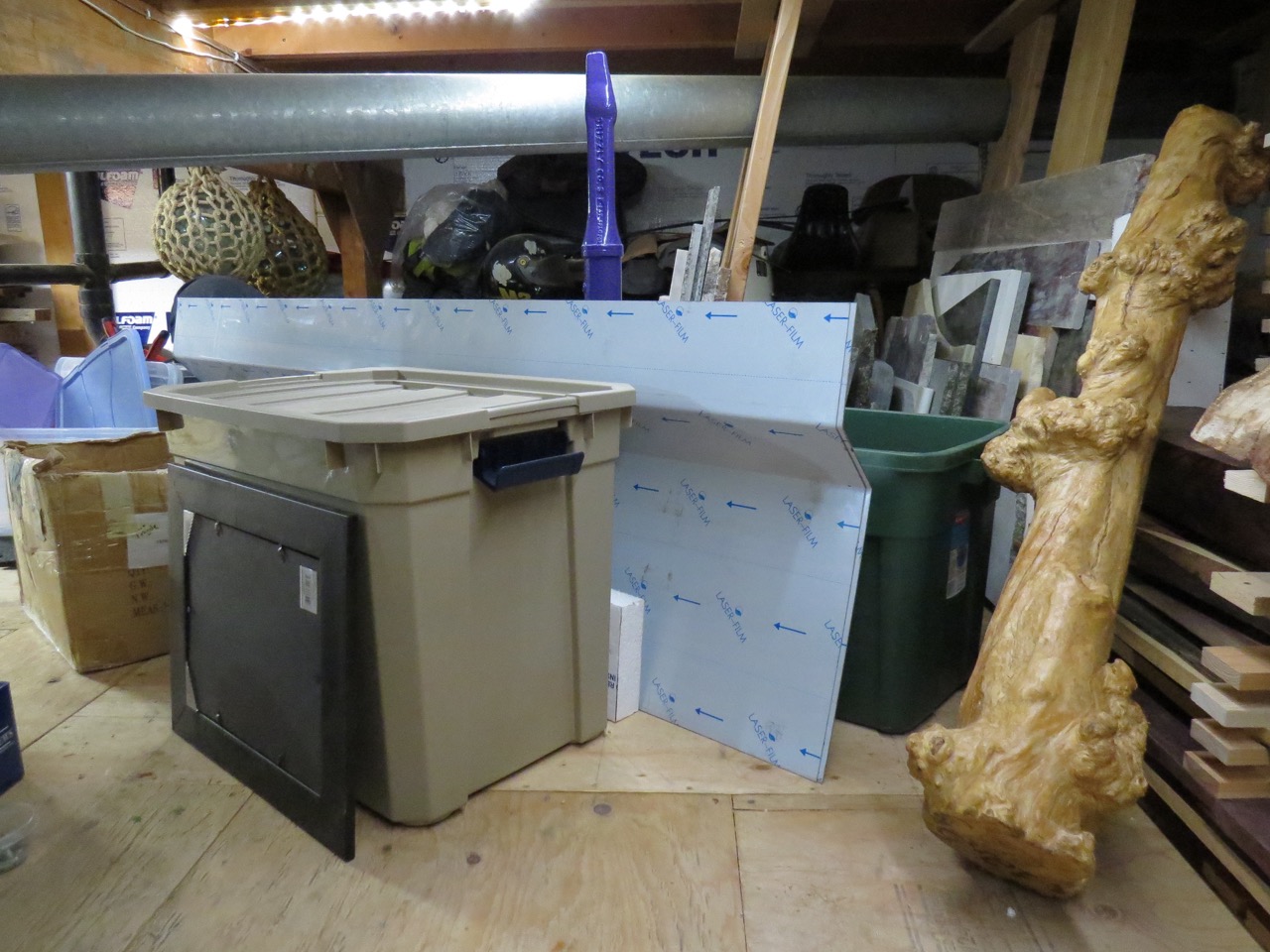
Also in the crawlspace are the duplicate sides and front and rear panels (18 gauge stainless steel) for the M100 trailer box. The gnarly looking hunk of what appears to be a dinosaur bone just to the right of the metal panels is actually an odd piece of wood from a coffee tree.

IMG_5111

 
To Top

Paul’s Putting on Powder

• CATEGORIES: Builds, Features • TAGS: This site contains affiliate links for which I may be compensated.

Take it away Paul ….

For the past couple of weeks I’ve been disassembling, cleaning, bead blasting and repairing parts for the little Willys and the M100 trailer so they would be ready to be powder coated.  I still need to install new wheel studs in the hub flanges along with pressing in the new bearing races but that task should be finished tomorrow.  The driveshafts need one to be shortened and one to be lengthened before they’ll go to the powder coater but progress is being made.

paul-powder-coating7

The blast cabinet is 48 inches wide overall and the axle is slightly over 53 inches long so I had a bit of a problem fitting the axle in the blaster and still having room to clean the rusty steel.  My solution was to leave the side door open and block the opening with multiple layers of cardboard (taped to the cabinet)  with a hole cut slightly larger in diameter than the brake backing plate mount on the axle to allow movement of the axle during blasting.  

Before I began blasting I added two more pieces of cardboard (cut to fit snug around the axle tube) to cover the larger hole in the cardboard end cover.  With this cardboard and duct tape combination I was able to carefully blast two thirds of the axle without filling the air with glass bead dust.  Once the axle section in the cabinet was clean I removed the axle, turned it end for end and inserted the rusty end into the cabinet to finish cleaning the metal.  This photo shows the low tech cardboard and cheap duct tape alteration of the blast cabinet so the axle blasting could begin.

paul-powder-coating6

The air compressor was blowing lots of air but the glass beads still had to work pretty hard to clean all of the rust off this 65 year old axle.  The metal is lightly pitted (especially on the forward side) but I don’t feel the original strength of the axle has been weakened in any way.  I checked the axle and the spindles with a straight edge and a level every 90 degrees of rotation to see if it was bent but the axle tube and the spindles are straight.

paul-powder-coating5

Here’s the axle just out of the blast cabinet ready to visit the powder coaters where it will receive a nice satin black coating.

paul-powder-coating4

Continue reading

 
To Top

Alaska WWII Jeep Hardtops & the YL-15

• CATEGORIES: Builds, Features • TAGS: , This site contains affiliate links for which I may be compensated.

Paul from Alaska wrote, “Recently I was at the Alaska Aviation Museum helping a friend assemble his plane when I noticed a very large photo displayed on the wall of the hanger.  As you can see this photo was taken in 1947 at Adak but what really caught my attention were the numerous flat fender Jeeps with hardtops driving on the base.  I took a close up photo of a cluster of these Jeeps even though the image is rather grainy but I thought you’d like to see it anyway.”

alaska-aviation-museum2

Labeling these 1 – 5 starting from the left, jeeps #1 and #3 look to have the same top. #2’s top is extended in the rear. #4 has no side windows. #5 I can’t see as well.

alaska-aviation-museum3

There’s a jeep near the top, again with a hardtop.

alaska-aviation-museum1

The full photo is in the background above the rare Boeing YL-15, which Paul’s friend has restored. The plane was built to win a military contract. The wings, tail and flaps come off quickly so the plane can be carried by a 6 by or towed by a Jeep.

Here’s an mocked-up example of a jeep pulling the plane:

jeep-hauling-yl-15-lores

And this shows a truck carrying it:truck-hauling-yl-15-lores

 
To Top

Paul’s M-100 Trailer Teardown

• CATEGORIES: Builds, Features • TAGS: This site contains affiliate links for which I may be compensated.

On another note, Paul has begun his tear down of an M-100 trailer, something he’ll rebuild in stainless:

paul-trailer-teardown2 paul-trailer-teardown3 paul-trailer-teardown1 paul-trailer-teardown4

 
To Top

Another Update From Paul

• CATEGORIES: Builds, Features • TAGS: This site contains affiliate links for which I may be compensated.

If I ever step into Paul’s jeep, I’m going to bring some surgical scrub footies.

Paul wrote, I felt the gray marine carpet in the footwells was too dark so I installed some stainless steel scuff plates on top of the carpet. I put a brushed finish on the stainless plates before I screwed them to the carpet and I’m happy with the results. The carpet is still visible, the stainless makes the footwell area brighter and I think the cutout design goes well with the Willys.

Just another crazy thing I never imagined I’d want for this Willys rebuild.

left-side-scuff-plates right-side-scuff-plates

2016-01-31-alaska

Those are some clear, blue skies!

 
To Top

Leaks & Fenders

• CATEGORIES: Builds, Features • TAGS: This site contains affiliate links for which I may be compensated.

Two bits of good news from Paul. One, his jeep was NOT affected by Alaska’s recent earthquake. He had the sense to bolt things to the wall that could potentially fall onto his jeep. Two, he’s made some more updates to Knardly Rolls! So, read on . . .

alaska-january-20162

Looking towards Anchorage and the mountains beyond, January 2016. This was pre-earthquake, though it pretty much looks the same after the earthquake.

Paul writes, the progress so far this winter season on the Willys has been a little weird. Things started to get strange when I decided to fill the cooling system for the first time in 30 years. I’m an optimist but I like to think I’m based in reality so I told myself there’s always the possibility of leaks in the cooling system and having a couple of empty buckets ready to catch dripping antifreeze might be a good idea. With the empty buckets cleaned and placed nearby I poured the first gallon of antifreeze into the radiator.

After a short pause to inspect the hoses and connections for system integrity I began pouring the second gallon of coolant into the radiator and I quickly noticed my feet were getting quite wet. I managed to wedge the empty but rapidly filling buckets under the front axle where most of the escaping antifreeze could be captured since the leak appeared to be from the front of the engine by  the timing chain cover. Oh well, it looks like yet another unexpected repair or modification needs my attention.

After the leak slowed down to a slight drip I repositioned one of the buckets directly below the radiator drain and began transferring the antifreeze from the cooling system into the bucket and then back into the gallon containers which is where this green fluid came from about 15 minutes earlier. When no more fluid flowed from the radiator drain and the recaptured antifreeze was safely back into the gallon containers I decided to call it a day and leave the heavy thinking for the tomorrow.

After having strange dreams throughout the night concerning the coolant leaks on the Willys, by the next morning I ready to start pulling components off the front of the engine so the timing cover could be removed for troubleshooting. Since the engine has never been run after being rebuilt this was a fairly quick and easy task.

Once the timing cover was out of the way and the front of the cylinder block could be inspected I learned an interesting bit of information about the Buick V-6 engine. The front of the block has 4 bolt holes (2 on the left and 2 on the right) for the timing cover to attach, BUT the timing cover is manufactured as either a 2 or a 4 bolt type.

paul-engine-plug2

The plugged bolt hole is the one closest to the right edge of the photo, it was left unplugged and partially exposed by the timing cover so the antifreeze flowed out quickly.

The timing cover on my engine is a 2 bolt type (where the coolant passage flows into the water pump) so the two unnecessary threaded holes in the block should’ve been plugged to prevent antifreeze from leaking. The unused threaded hole on the block is drilled into the coolant passage but the unused hole to the right is a blind hole and not open to the cooling system.

To prevent anymore leaks and to make me feel better I installed internal wrenching hex plugs in the unused holes . These plugs were screwed into position after the threads were cleaned and dried and the threads on the plugs were coated with gasket compound, then it was time for reassembly. Things were going pretty well until I noticed the rubber on the crank pulley damper was cracked and bulging out along the seam so this project came to a halt until the damper made a trip south to the Damper Doctor for a rebuild. 

[editors note. I *think* it was in one of those holes that, during my very first engine rebuild, I put too long of bolt into one of the holes. I tightened it down, though it got difficult near the end. Imagine my surprise when the #1 cylinder piston kept hitting something while i tried spinning the crank. OOPS, I’d damaged the cylinder wall!!]

paul-clamps-fender

Two pieces of 3/4 inch plywood spread the clamping pressure and prevent damage to the metal when installing the abrasion panels to the underside of the fender.

Continue reading

 
To Top

Knardly Rolls is Close to Road Ready

• CATEGORIES: Features • TAGS: This site contains affiliate links for which I may be compensated.

Paul’s getting close. Over the last six years we’ve watched him build this stainless monument to jeeps. Just some little things to be completed. Maybe 2020????

paul-m38-1 paul-m38-2 paul-m38-3

 
To Top

Paul’s Stainless Wheel Covers

• CATEGORIES: Builds, Features • TAGS: This site contains affiliate links for which I may be compensated.

With winter settling into Alaska, Paul has returned to continue work on his Stainless M-38 (and a matching stainless trailer). I believe this is the 28th year of the project? Thanks for sharing Paul!

paul-wheels8

Knarley Rolls, Paul’s M-38. The spare with its cover is attached to the back of the jeep.

The black steel wheel in the photo below is one of 8 new wheels I purchased for the Willys (4 and a spare) and the M100 trailer (2 and a spare) so I need to modify these wheels to accept the stainless wheel discs I previously made. Each wheel will have 6 metal tabs (evenly spaced) welded to the outer face of the wheel with the tabs running from the outer bead flange to the raised inner ring around the lug nut area and each tab will have two nuts welded to the inner surface. These nuts will line up with holes drilled thru the stainless wheel discs to accept the wheel disc attach hardware and the tabs will provide additional support to hold the wheel discs while driving.

paul-wheels1

The black rim is to the right covered by a template. The other parts are trailer pieces from the disassembly of his trailer.

My original plan was to have only one nut per tab (so the wheel disc would be held on with six machine screws) but it’s much easier to weld two nuts to each tab while I’m making the parts than to have to add additional nuts and attach screws after the wheels have been powder coated just in case the discs wobble during rotation. I’ll try the 6 attach screws per wheel first and if the wheel discs stay smooth during driving I’ll leave the extra 6 nuts empty. If the disc shows any sign of instability while driving I’ll use all 12 screws to attach the disc for extra support.

paul-wheels2 paul-wheels3

Continue reading

 
To Top

Paul’s Shielding the Heat

• CATEGORIES: Builds, Features • TAGS: This site contains affiliate links for which I may be compensated.

Paul built a heat shield to protect his steering assembly. I believe it’s his last project of the winter. Paul’s putting ‘Knardly Rolls’ to rest until Fall. It’s now time for him and the Goddess to drop the top on the Miata and explore the melting tundra.

He writes, Here’s the heat shield I made to protect the steering assembly from the heat given off by the left exhaust manifold and exhaust tubing. As you might have noticed there’s very little clearance between the heat shield and the steering shaft.  A penny will not fit between the heat shield and the steering shaft. The heat shield is .020” stainless and the attach bracket which clamps to the exhaust pipe is .050” stainless.

paul-heatshield2

The decreasing diameter holes drilled thru the attach bracket will allow cooling air to pass behind the heat shield which will help keep the steering linkage from getting too hot. I hope. The brown coating on the brake light switch ground wire attach bolt is a gasket shellac that should prevent water from seeping between the ground wire connection to the bare frame so corrosion is prevented. The exhaust is held to the manifold by silver plated high temperature steel self locking nuts.

paul-heatshield1


To Top

Wheeling Discs and New Tires

• CATEGORIES: Builds, Features, stainless/jewels • TAGS: This site contains affiliate links for which I may be compensated.

Paul continues to make progress on his jeep. He received his tires and has made some custom stainless rim discs.

tires

Paul’s new tires

TIRES:

He writes, “The New Tire Fairy arrived at the house today with eight brand new STA Super Traxion 6.50-16 tires along with eight new inner tubes for the little Willys. I’d been searching the internet for a vintage looking narrow tire with an aggressive tread design that would look good on the Willys so shortly after I discovered these tires I put my credit card to work and placed my order.

I wanted to replace the brand new but 30 year old tires on the Willys so that accounted for 5 tires and I needed 3 more tires for the military trailer (I want the trailer to have it’s own spare tire) so that’s why I bought eight. Shipping wasn’t too expensive since I wasn’t in a hurry and compared to Coker tire who wanted to ship their tires 2nd day air ($1,100 for the tires and an additional $900 for shipping) it was down right reasonable by Alaska standards.”

WHEEL DISCS:

wheel-discs-test

In this photo he’s testing out the disc concept with poster board.

He writes, “I bought some poster board that was large enough to make full size mock ups of the stainless steel wheel covers I’m thinking of making to cover the plain steel wheels I’ll be using on the Willys. The six larger holes are 1 & 1/2 “ diameter and the smaller holes are 1 “ in diameter. I’ve made other discs, some with more holes and some with less holes on each disc in various patterns but I keep coming back to this design. It’s simple, the spacing of the holes is easy on my eyes and the wheel covers make the tires appear larger and more heavy duty.

Each hole will have a reinforcing ring fastened to the back side of the disc either by 1/8th inch diameter monel raised head style rivets or 3/16” dimeter stainless steel machine screws (the size of the machine screws used on the door just below the window). These doublers and rivets are for style only and not necessary for strength. Each disc will be attached to a wheel by six stainless machine screws and these screws will thread into steel mounts welded to the wheels.”

wheel-disc1

A completed disc.

“Above is the first wheel disc with the holes drilled and the rivets installed. I gave the plain disc a brushed finish to see what it would look like … I think it’s about as close as I can come to matching the body finish. These wheel discs need to be easy to clean and easy to touch up the finish so a mirror polished disc would require lots of maintenance to keep the metal shiny. I don’t have enough energy to keep up with the mirror finish. 

I finished riveting the last two wheel discs today then I cut a hole thru the center of the front wheel disc slightly larger than the Warn hub so these discs could be test fitted to the wheels on the Willys. The tires on the Willys are still the old new ones and not the new, new ones I recently received since the steel wheels currently on the Willys have the wrong offset and will be replaced with the correct wheels in the near future. Anyway, I think these discs match the Willys much better than the aluminum wheels I was originally planning on using.”

wheel-disc2

The wheel discs attached. The discs came out a little darker, but that’s probably because of the angle. The discs are made of the same stainless as the rest of the jeep. These are the old tires, not the new ones.


To Top

Paul’s Getting All Charged Up

• CATEGORIES: Builds, Features • TAGS: This site contains affiliate links for which I may be compensated.

Paul’s made some additional progress over the last month on his stainless jeep.

Paul writes, The upholstery is done, the driver’s seat has been installed and the seat belt/shoulder harness combos have been adjusted for length and bolted in place. The passenger seat will still need to be removed to allow access to the battery mount and cable connections in the electrical box but progress is being made.

interior-stainless-paul

Corbeau three inch wide belts with a cam lock release and in a color that goes well with the upholstery and stainless steel.

interior-stainless-paul2Paul has also been working on the battery installation. He continues, The open space on the right side of the electrical junction box should be filled with a new Odyssey AGM side post battery

battery-box1

Here I’m comparing the size of the Odyssey battery to the mockup battery I taped together out of poster board. I used the mockup battery to locate the attach points for the battery hold down bracket in the electrical junction box.

battery-box2

The battery fits and there’s even room for a longer battery. This small battery weighs 45 pounds so I don’t believe there’s any need to get a larger and heavier battery anytime in the future.

battery-box3

This hold down bracket is slightly bigger than the battery but the battery is firmly held when the attach hardware is tightened. The bracket consists of eight separate pieces of stainless held together by 40 rivets.
battery-box4

Now it’s time to start smoke testing the wiring and that might take a while.

 
To Top

Paul’s Getting Serious

• CATEGORIES: Features, stainless/jewels • TAGS: This site contains affiliate links for which I may be compensated.

Paul really seems serious about finishing his jeep! Below he shares photos and updates:

All sidewall and top upholstery panels have been installed so I began cutting foam for the front seats.

2014-10-15-paul1

Still waiting on the carpet for the rear wheel well tops, the rear floor and the front seat footwell areas.

2014-10-15-paul2

Here you’re looking at the rear window panel and the left rear wheel well. I think the gray fabric and the stainless steel look pretty good together.

2014-10-15-paul3

I’m looking forward to getting the seats upholstered. The gray and blue seat colors should add a bit of color to the interior.

2014-10-15-paul4

Front seats reinstalled, the foam is rough cut and the combination of thick foam for the bottom and thin foam for the back will allow enough room for me to reach all of the controls and still see out the windshield. The side windows are another matter. I should have Sumo-sized my Willys.

2014-10-15-paul5

 
To Top

More Progress From Paul

• CATEGORIES: Features • TAGS: This site contains affiliate links for which I may be compensated.

Paul’s added more panels to his M-38. The gray panels look real nice inside. Somehow, he managed to arrange an earthquake in Alaska just to test the design!

paul-upholstery-m38-6

I purchased more shower curtain rods so I could speed up my progress on installing the Willys interior panels. I’m excited seeing the improvement the fabric panels make over the bare stainless and it seems Mother Nature is excited also. Yesterday (Sept. 25th) we had a 6.2 earthquake rumble thru town and this evening we had another smaller earthquake measuring only 5.0. The 6.2 quake managed to knock some stuff off the shelves in the garage and some items stored in the crawlspace were broken but we had no damage to the house or the Willys so I’m a happy guy. Here’s a picture of two more interior panels being held in place by 10 curtain rods (upholstery tensioning devices) and you can see the gray fabric panel slightly above the center of this photo. Tomorrow I’ll install two more overhead panels and prep the two vertical corner pieces if the earth quits moving long enough for me to reposition the tension rods.

paul-upholstery-m38-5

As you might have noticed, I clamped the rear window upholstery panel into position this morning. The interior panel is protected by a 2 inch thick white foam overlay and cardboard taped to the stainless protects the surface from scratches from the vise grip clamps. paul-upholstery-m38-4

Two inch thick foam overlay protects the upholstery panel and spreads the clamping force. Two smaller finished pieces are installed and clamped by the famous adjustable tension rods. I’ve used 34 tubes (12.9 ounces each) of black silicone to attach 15 interior panels and I still have 18 panels left to install.

paul-upholstery-m38-2

I never expected shower curtain rods and foam insulation were necessary tools for installing upholstery in the Willys. As you can see on the right Vise Grips, thin plywood and pink foam are also needed. Yes, we embrace diversity here in the northland. paul-upholstery-m38-1


To Top

Paul’s Back Playing with his Willys

• CATEGORIES: Features • TAGS: This site contains affiliate links for which I may be compensated.

With the return of cold weather to Alaska, Paul’s back in the garage putting some finishing touches on his long-time project.

Paul writes,
All the wood projects are put away for the winter and I’m back working on the Willys fitting upholstered panels to the interior. Sheets of white high density foam have been cut into the necessary shapes and (depending on their location) either covered with fabric or bonded to .050″ stainless steel. A silver/gray fabric will be used on most of the interior but six panels (three on the left and three on the right) will be attached to metal pieces for extra abrasion resistance in the front seat footwell area. I’ve coated the inside of the Willys with 2 layers of black silicone but I still need to apply the silicone to the open cell interior foam before I can begin installing the upholstery. My plan is to work from the top down so the six overhead panels will be the first fabric covered sections to be installed. Since the silicone takes 24 hours to cure I needed to come up with an easy way to hold these pieces in position while the silicone cured.

footwell-panels

The shower curtain rod, oops I mean the upholstery clamping fixture is pressing against the foam block holding the kick panel in position.

The Goddess suggested I lay on my back inside the Willys (just aft of the front seats) where I could hold four panels in position using both my hands and feet. She said 24 hours isn’t that long to stay in one position and after all I’d be laying on my back so it’s not like I’m doing any work or anything like that. Even her offer to bring me some food and a blanket for the night hours wasn’t enough to convince me this was a good idea so I attempted to find a different solution. What I wanted was an adjustable length tube where the clamping force could be increased or decreased as necessary and it should be reasonably cheap. Time to visit Lowes and wander the aisles to see what I could find. The solution to my problem was waiting for me in the bathroom fixtures aisle where I saw a fantastic display of assorted length adjustable shower curtain rods. They were designed as shower curtain rods, they were manufactured as shower curtain rods and they were sold as shower curtain rods but now they were Willys upholstery installation tools. The best part of this deal was the low price of each upholstery tensioner allowed me to buy four long ones (44 to 72 inches in length) and three short ones (24 to 48 inches in length) without spending very much money. I was happy and my back was happy.

interior-upholstery

Since I was going to be climbing into and out of the Willys a lot I removed the front seats and the fuel tanks so I’d have more work space.

Today I positioned one of the long tubes from the interior of the left side of the Willys, across the transmission tunnel and over to the right side footwell to provide clamping pressure on the abrasion panel. It worked GREAT! There were two more metal clad panels ready for installation (below the door openings) but here I used adjustable clamps along with some small foam board pieces to spread out the clamping force during installation. I’ll send you pictures to go along with my words so you’ll have a better idea of what I’m doing.

interior-upholstery2

Since I was going to be climbing into and out of the Willys a lot I removed the front seats and the fuel tanks so I’d have more work space.

interior-upholstery3

Notice the black silicone trimmed from the edge of the window opening? I still have a little cleaning to do in this area.

To prevent problems with the upholstery I removed the glass from both side windows and the rear window before I applied the black silicone on the interior of these top panels. Not having the glass installed made applying the silicone much easier but I managed to smear silicone where the rubber H channel (used to hold the glass to the metal panels) grips the metal edge. While I let the silicone cure I thought about how I could carefully trim the unwanted silicone from the window opening on the top panels. I could use a razor blade and make the cut free handed but I was hoping to be a little more precise than that so I dug thru my tool box and I came up with a simple but accurate solution. I found an old compass (the circle kind, not the where are we kind) and after removing the pencil I was able to fit a clone of a small Exacto knife where the pencil would go. Using the center pivot as an edge guide I adjusted the blade position by using the knurled knob so the cut would be made slightly past the edge of the rubber H channel. A quick pass around the window opening and the silicone was trimmed back the needed amount.

special-edge-trimmer

This little cutter worked great, I lucked out and had a cutter that was the same diameter as the average pencil so everything fit together with no problems.