Builds Research Archives

To Top

2004 “Corveep” Build

• CATEGORIES: Builds, Features This site contains affiliate links for which I may be compensated.

Here’s a unique build that married a wrecked 2004 Corvette with a free 1968 Jeepster Commando. The builder calls it a “Corveep”. There’s a series of pics that document some of the challenges involved in marrying the two vehicles, including lengthening the Commando body.

http://bobpelikan.com/?p=54#more-54

2004-corvette-commando-corveep

 
To Top

Jane Bundy’s 1947 CJ-2A

• CATEGORIES: Builds, Features This site contains affiliate links for which I may be compensated.

This nice looking CJ-2A wasn’t restored to 100% original, but it sure looks nice and will provide owner Jane Bundy with a great vehicle for years to come. The Miller Brothers Hot Rod Barn in Wilkesboro, NC, did the work.

https://statesville.com/news/local/my-classic-car-jane-bundys-1947-cj-2-willys-jeep/article_0b29b0b2-2394-11eb-a8cb-9f13bbeae594.html

1947-cj2a-jane-bundy

 
To Top

A Turbo Hayabusa Suzuki Powered Jeep Build

• CATEGORIES: Builds, Features, videos This site contains affiliate links for which I may be compensated.

Bill shared this post from thedrive.com about a youtuber named DJ (youtube channel Limitliss) putting a Turbo 1.3 liter Suzuki Hayabusa engine into a jeep-rod build. He was originally going to install a ZX10R, but found it to be too damaged to proceed, so he switched to the Suzuki engine.

https://www.thedrive.com/news/37571/a-turbo-hayabusa-powered-willys-jeep-is-enough-to-make-you-forget-ls-swaps-forever

Here’s Limitliss’ ‘reveal’l of the jeep build, but it’s not the first episode (call it episode 0):

This is episode 1:

You can follow the rest of the build here: https://www.youtube.com/playlist?list=PLNbNJv69UAARr6Sqxaq-RqBM10eKKaYkp … there are currently 19 episodes.

 
To Top

Willys Truck & 2014 JK Chassis

• CATEGORIES: Builds, Willys Trucks This site contains affiliate links for which I may be compensated.

UPDATE: apparently, this one is up for sale

This nice looking truck is a Willys body and look adapted to a 2014 JK Chassis. No doubt it cost a few bucks to assemble. The result sure looks nice. Note that the whole truck had to be widened.

See all the pics here: https://www.quadratec.com/c/blog/brothers-challenge

Some of the stats:

  • 1955 Willys Truck mounted on 2014 JK chassis
  • 118” wheelbase
  • 4800 pounds
  • 3.6 Pentastar with RIPP Supercharger
  • Automatic transmission
  • 440 hp at crank
  • Dual exhaust with catalytic converters.
  • Fuel 17” wheels
  • Toyo Open Country C/T 35” tires
  • 3.5” Rock Krawler Long arm lift kit
modified-truck-moab

PHOTO CREDIT: Quadratec.com

 
To Top

1955 Truck Project

• CATEGORIES: Builds, Features This site contains affiliate links for which I may be compensated.

Bud Wilkinson of the Republican-American reported on this Willys Truck rebuild. https://wheels.rep-am.com/2020/07/my-ride-out-of-the-dump-and-into-the-willys-jeep/

 
To Top

The Jeep-Engine Powered Chum

• CATEGORIES: Builds, Features This site contains affiliate links for which I may be compensated.

Gayland shared this do-it-yourself boat project that’s designed around a jeep-engine. It’s called the Chum. Below is the first page. Download the PDF to see all the instructions. There’s even a Willys marine engine for sale right now.

https://www.diy-wood-boat.com/support-files/chum.pdf

 
To Top

The Hudson Hornet Steering Modification

• CATEGORIES: Builds, Features This site contains affiliate links for which I may be compensated.

Just a few posts today, but some good ones!

hudson-swap-adam3-lores

1951-1953 Hudson Hornet steering box installed on John’s CJ-2A.

I’ve been very interested in the Hudson Hornet Steering Modification since I heard about it a decade ago. Unfortunately, there’s scant information about implementing the modification, but reports were that it was a relatively easy one that produced fantastic results, offering a power-assist feel to the steering and reducing play (a similar, alternative steering modification is the use of a 1980s Ford Ranger box, which Lawrence Ellliot shared back in 2018).

Now, thanks to Adam, we have some new insights into the obstacles and benefits of installing a Hudson unit into a vintage jeep! Perhaps the most difficult obstacle to overcome is locating the steering box itself! Adam’s provided some great details below, but If you want to ask Adam more questions directly, he’s offered his email ahedgcock @ gmail.com (remove the spaces around the @).

Below, Adam shows some of the differences between the Hudson and Ross (Willys) units:

hudson-steering-box-willys-box-differences

Here’s Adam’s description:

  1. Find box. Perhaps the most difficult task .. 51 to 53 Hudson Hornet.
  2. Pitman Arm/Get Drag Link. Try to get the bell crank and drag link. The Hudson splined pitman shaft is quite a bit larger than the willys splined shaft so it is good to use the original. The pitman arm itself is similar in how it bends, but is 7” long ( instead of 5” on the willys)
  3. Pitman Arm Ball. The pitman arm ball end on the Hudson is larger than the willys, so I welded the Hudson drag link end onto my willys drag link.
  4. Hudson Box bolts right up, but …The Hudson box could be bolted directly to the frame rail with 3 bolts, but the steering column will be 2.5” too far on the drivers side to hit you body tub hole. Having all stock brake and clutch pedals, and not wanting to make my tub Swiss cheese, I chose to move the box 2.5” off the frame with a fabricated spacer. This would be similar to the level of fab needed to convert a Saginaw box up front.
  5. Or Shift the Hudson Bracket. The cast steel Hudson bracket could be cut and re-welded to the box 2.5” over also, with the same results.
  6. Modify the Column Tube. The steering column is similar to the willys but the Hudson column tube is larger than the Willys. I welded a larger OD sleeve at the base of an existing willys column, cut a split in it and welded on 2 ears so I could clamp it tight.
  7. Steering Shaft Differs. The steering shaft does not have the same end spline for a willys steering wheel, so you can either cut and weld a willys spline to the end, or find a Hudson steering wheel.
  8. Gear ratio. I did not take the box apart, but it is clearly a roller bearing worm shaft, and this thing came tight, even after presumably many years of use. The Hudson box is 6 turns lock to lock, and the Ross is 3 turns. It is worth noting the pitman arm is longer, 7” vs 5” on the willys, but you get a definite advantage in ratio. A bit less than half the effort to turn the wheels. I have taken it on road, and there is not the same “twitch” at speed, and off-road it does not tear your thumbs off like before. The wheel still happily spins back to center by itself nicely when you let it go, just more revolutions.
  9. Placement of box. This will be subjective, I have a Buick V6 and I found the longer pitman arm worked better because it swings below my bellhousing rather than ramming I to it with the Ross. Just like placing an engine, you would want to mock up the ideal spot, and make the bracket accordingly.
  10. Original look. This is basically a similar box, and does not effect the outward appearance at all.
  11. Finding parts…this is the fun part, I needed to talk to people, and ultimately find a person willing to go digging through an old barn. Once I found my source, I bought 2. Paid $200 each.
  12. Very fun swap, more original than the Saginaw, similar performance to a manual Saginaw provided to have a good tight bell crank and good tie rod ends.. I don’t see any need for a steering stabilizer

Hudson Horney Box casting number 34641.

hudson-steering-box-casting

Continue reading

 
To Top

John’s Cutlas Selective Hub Rebuild

• CATEGORIES: Builds, Features, How To • TAGS: This site contains affiliate links for which I may be compensated.

John recently rebuilt a set of Cutlas Selective Hubs, the type with the knob that rotates to engage and disengage the hub. There appear to be at least two styles of these hubs, one with a flat top and one with a groove, so that a tool (or improvised tool) can be used to help engage, disengage the hub.

This exploded overview from 1961 shows how the parts assemble (see the full brochure below this post):

1961-12-01-cutlas-selective-drive-model100-2-partial-lores

As you can kind of see from this diagram, there are two sections: 1) is the hub cap that holds the knob and the spring in place (from part 107-2 in the middle and everything to the right of it) and 2) the hub base (part 108-2 and everything to the left of it).

John wrote, “Overall I’d say these are my favorite hubs I’ve worked on so far. I have a pair of Warn hubs (with the tiny needle bearings) and a pair of Selectro hubs (big chrome knob type). The Warns seemed like a real pain to rebuild since the needle bearing were in rough shape. And the Selectro hubs, while very easy to operate, were probably the weakest design I’ve seen.”

Here’s a look at John’s finished product, as it’s the best example a complete hub next to a hub with the top separated from the base:

cutlas-hub-groove-rebuild-john8-lores

I went with a 2 tone paint job just for fun. If it doesn’t last for any reason I’ll end up with the whole thing gloss black and a chrome knob. The body was so badly pitted there was no saving the original finish

HUB CAP:

We’ll start with the hub’s cap first. John provided the following note: “To remove the coupling piece (part 102-2 Coupling) from the chrome cap (with the cutlas knob) you have to line it up right with the correct groove, then push down firmly against the spring inside (part 110-2 coupling spring). While pushing down spin the coupling, and then the coupling spring will pop the coupling right out and its free.”

cutlas-hub-groove-rebuild-john3-lores

cutlas-hub-groove-rebuild-john4-lores

With the inner portion of the cap apart, you can see the coupling ring, the coupling, the coupling cam spring (part 107-2) and the coupling cam pins (parts 105-2).

cutlas-hub-groove-rebuild-john2-lores

Continue reading

 
To Top

Dan Details the Thor “Lectro-Matic” Hub

• CATEGORIES: Builds, Features This site contains affiliate links for which I may be compensated.

UPDATE: I posted this Thor post over a decade ago (how times flies). Below is a look at the switch used to engage the Thor “Lectro-Matic” Hub, which came from this post. Since the below post was first published, there’s also been some history about Thor Products on a shared on another post.

thor-auto-hubs-switch

==========================

Originally posted January 2010: 

Dan dropped this into my inbox this evening.  It’s a detailed look at the Thor “Lectro-Matic” Hub (or lectromatic hub). Dan completed this 18 page document, with disassembling the hubs and discussing each step.  You can download the PDF here Great work Dan!

Dan writes, The Thor “Lectro-Matic” hubs off of my 1955 CJ-5 were a bit of a mystery. These must have been some of the first “push button” 4WD systems to come out. There was little to no information on them so I decided to take them apart and see just how they work. Here is what I have learned.

When my Dad said that they were electric, I assumed that they had a little motor that would “spin” them in or out of engagement. What I realized was that they were more like a solenoid or electromagnet.

There is a coil of wire on the wheel side of the hub. When power is applied to the coil it becomes a magnet and draws itself to the axle side of the hub. There are little “teeth” machined into the facing sides of the hub. These teeth engage and the axle side of the hub turns the wheel or magnet side of the hub. A wire is ran through the back of the backing plate through a hole and provides the electricity to the magnetic coil. A contact mounted on a spring transmits this electric power through a slip ring inside the brake drum to the hub.

I imagine that the hubs could be engaged while the vehicle is moving, but I think this would cause the teeth to slip for a moment and lead to premature wear of the teeth. A toggle switch or a maintained push button could be used to turn the hubs on and off. One could even use a limit switch on the 4WD lever of the transfer case to automatically turn them on when the vehicle was shifted into 4WD. The hubs would only remain engaged as long as power is applied to the magnetic coil. If you left the switch on and had run power directly off of the battery to the switch, it would eventually drain your battery after the engine is shut off. If you ran power from the ignition switch to the on/off switch, your hubs would automatically disengage as soon as you shut off your engine.

If for some reason they didn’t want to work, there was a little screw on the outside face of the hub that you could turn to manually engage or disengage the hubs (as you can see below).


On the top of the hub you can see the wire that passes through the brake drum to power the magnetic coil.

Download and read the entire document here

 
To Top

Bob’s Longtime Militarized CJ-2A

• CATEGORIES: Builds, Features This site contains affiliate links for which I may be compensated.
GE

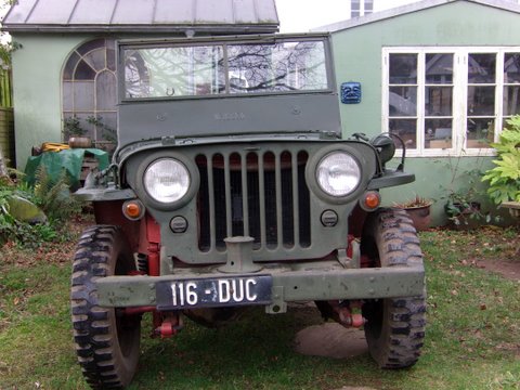
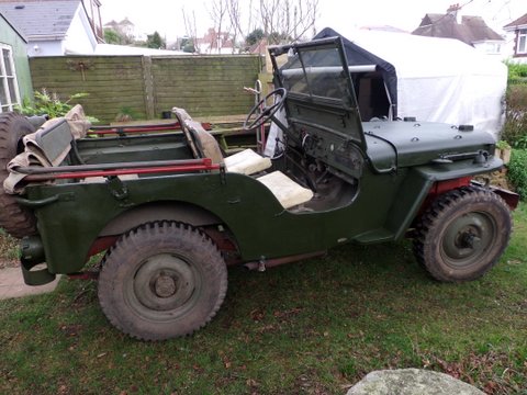
Bob Le Marchant’s militarized CJ-2A

Bob Le Marchant discovered eWillys last month. Now 72, below he shares some tales with his beloved CJ-2A.

Bob started jeeping at age 17. His ‘crazy neighbour’s’ father (an ex-submarine captain) ran a yellow Ford Jeep. He dearly wanted one too, but ended up with a 1946 CJ-2A. It was not only his first jeep, but also Bob’s very first vehicle. Metamet, a British company that offered a wide variety of modified WWII jeeps, soon became his central place for purchasing spare parts. He loved going up to London and finding Daleham Mews.

The CJ-2A, being his first vehicle, was what he used to pass his driving test (the tester spent the whole test reading the dash plates and talking about Jeeps … he had driven jeeps in the war). As a teenager, Bob discovered there were two sorts of girls: the ones who looked crest fallen and said ” Oh, shame it isn’t a little sports car”, and those who said “Wow!! Where shall we go in that!”

GE

GE

After graduating as a mining engineer (he proudly notes that Ben Carlin was one too), he shipped his Jeep out to South Africa to work. For a while he worked near Johannesburg in what was then the second deepest mine in the world at 11,700 feet. Bob wrote that, “At that depth the intrinsic rock has a hydraulic pressure: the floor is as much likely to burst up as the roof fall down. Square tunnels soon become circular as shards come off. The natural rock temperature is 150 degrees or so, with 100% humidity. Heat stroke was the main killer down there. Everything he has  ever done since then has been a “piece of piss!”

Later, in the 1970’s, he DROVE his jeep back to the UK to do work a job blasting a tunnel for the Ffestiniog Railway in Wales. However, to get to Wales, he had to take the long way because, due to politics, he couldn’t get north of Kenya, so he shipped his jeep to Bombay, then drove northwest via Kyber Pass and Istanbul.  The adventure was a trip of a lifetime.

“This Jeep has travelled,” he noted. Unfortunately, his ex-wife has all the pics.

GE

GE

GE

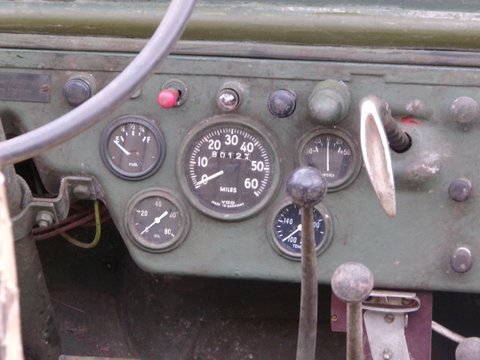
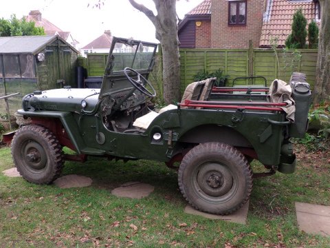
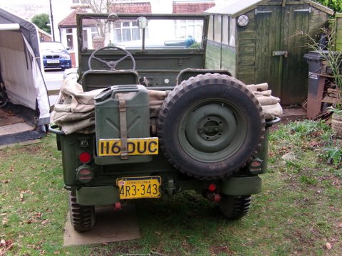
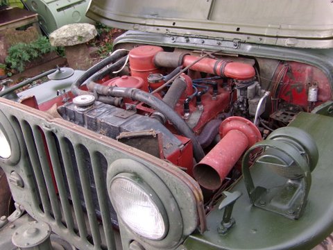
Currently, he lives in Devon in South West England. His longtime CJ-2A is still a very road worthy, nearly everyday vehicle. The engine uses a Hotchkiss block. He also has a Metamet dash plate on the wall. He loves his jeep!