How To Research Archives

How To

To Top

1956 French-Canadian Ad From Kaiser-Willys of Canada on eBay

• CATEGORIES: Advertising & Brochures, Features, How To, International • TAGS: This site contains affiliate links for which I may be compensated.

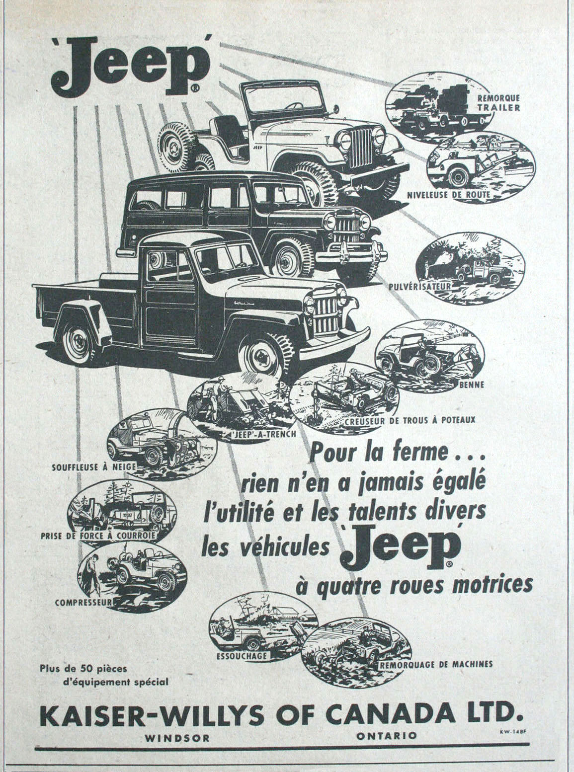
Maury spotted this jeep-family ad from Kaiser-Willys of Canada.

View all the information on eBay

“1956 Canadian Kaiser Willys print ad Jeep Universal, Wagon, & Pickup. Original magazine advertisement measures 7 X 9.5 inches (approx.).”

1956-kaiser-willys-canada-ad-jeep-family2

 
To Top

John’s Cutlas Selective Hub Rebuild

• CATEGORIES: Builds, Features, How To • TAGS: This site contains affiliate links for which I may be compensated.

John recently rebuilt a set of Cutlas Selective Hubs, the type with the knob that rotates to engage and disengage the hub. There appear to be at least two styles of these hubs, one with a flat top and one with a groove, so that a tool (or improvised tool) can be used to help engage, disengage the hub.

This exploded overview from 1961 shows how the parts assemble (see the full brochure below this post):

1961-12-01-cutlas-selective-drive-model100-2-partial-lores

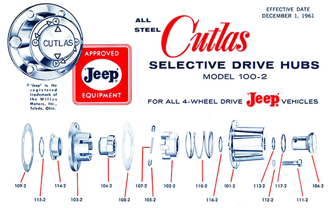
As you can kind of see from this diagram, there are two sections: 1) is the hub cap that holds the knob and the spring in place (from part 107-2 in the middle and everything to the right of it) and 2) the hub base (part 108-2 and everything to the left of it).

John wrote, “Overall I’d say these are my favorite hubs I’ve worked on so far. I have a pair of Warn hubs (with the tiny needle bearings) and a pair of Selectro hubs (big chrome knob type). The Warns seemed like a real pain to rebuild since the needle bearing were in rough shape. And the Selectro hubs, while very easy to operate, were probably the weakest design I’ve seen.”

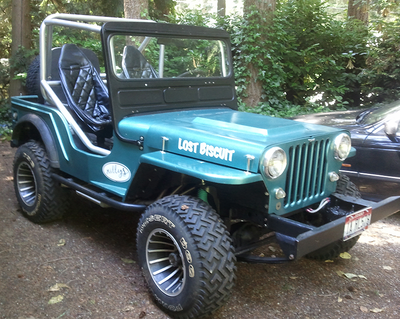
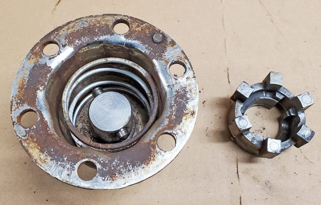
Here’s a look at John’s finished product, as it’s the best example a complete hub next to a hub with the top separated from the base:

cutlas-hub-groove-rebuild-john8-lores

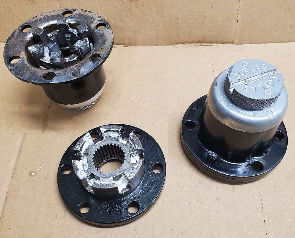
I went with a 2 tone paint job just for fun. If it doesn’t last for any reason I’ll end up with the whole thing gloss black and a chrome knob. The body was so badly pitted there was no saving the original finish

HUB CAP:

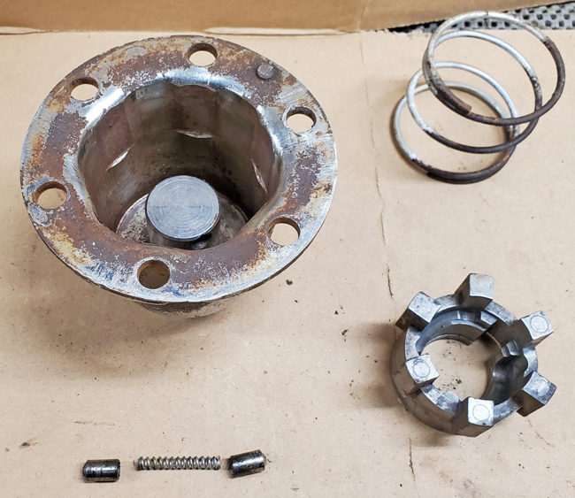
We’ll start with the hub’s cap first. John provided the following note: “To remove the coupling piece (part 102-2 Coupling) from the chrome cap (with the cutlas knob) you have to line it up right with the correct groove, then push down firmly against the spring inside (part 110-2 coupling spring). While pushing down spin the coupling, and then the coupling spring will pop the coupling right out and its free.”

cutlas-hub-groove-rebuild-john3-lores

cutlas-hub-groove-rebuild-john4-lores

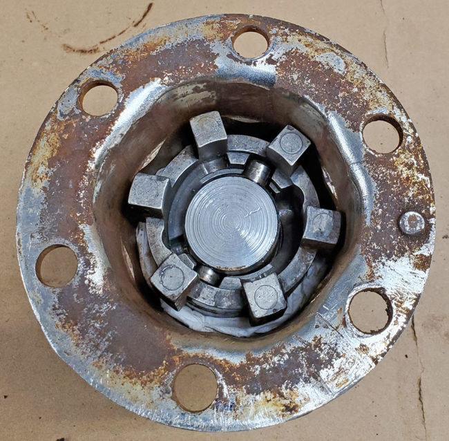
With the inner portion of the cap apart, you can see the coupling ring, the coupling, the coupling cam spring (part 107-2) and the coupling cam pins (parts 105-2).

cutlas-hub-groove-rebuild-john2-lores

Continue reading

 
To Top

Rebuilding the Ross Steering Box

• CATEGORIES: Features, How To This site contains affiliate links for which I may be compensated.

ross-steering-gear
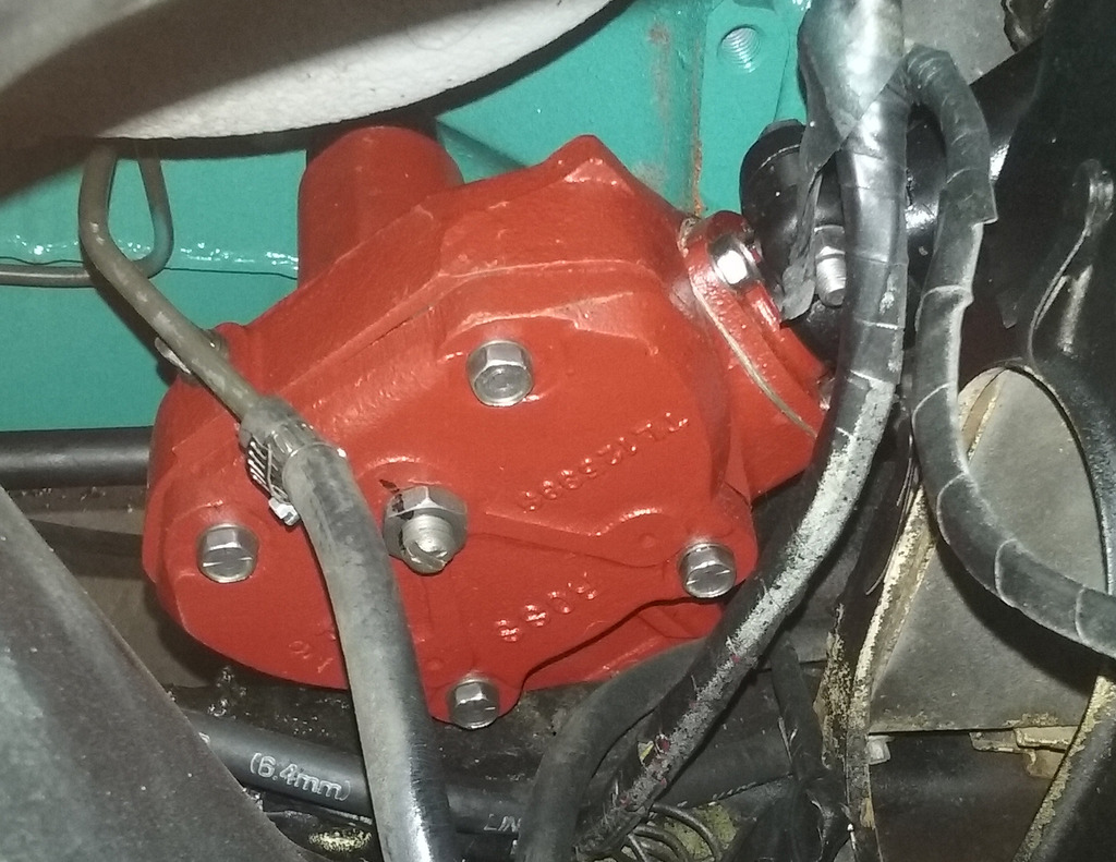
Maury published a forum-thread on rebuilding his Ross Steering Box. He (and I) thought you all might find it interesting, too. He also wanted to ackowledge Moses Ludel for all his help (read their exchange here).

This is the link to their subsequent installation & alignment thread: http://forums.4wdmechanix.com/topic/747-ross-tl-steering-gear-installation-and-wheel-alignment/

Here’s a note about Maury’s experience:

I suspect everyone knows who Moses Ludel is, as he has been involved with jeeps at a professional level for several decades. As you may be aware, he has written several excellent books on jeep rebuilding and maintenance, including the Jeep CJ Rebuilders Manuals and the Jeep Owner’s Bible. He is the administrator of the 4WD Mechanix website as well.

The original Ross TL steering gear in my 1967 V6 CJ5 badly needed rebuilding, and I really wanted to accomplish this with NOS parts to the greatest extent possible. Late last year, in researching possibilities for having the rebuild work done professionally, I came across a video on Moses’ website about rebuilding the Ross boxes in which he rebuilt one for a client. I contacted him to ask if he was still doing that kind of work on the side. He responded that he is not, but in short order, he got me interested in doing the rebuild myself. Moses offered to assist me through the process by helping me create a pictorial thread on his website, through which he could advise me as I worked through it one step at a time.

The resulting process of finding the parts and fully rebuilding and installing two Ross TL boxes (mine and my brother in law’s) is thoroughly documented in the two threads linked to above. The first thread is on the rebuilding process itself, and the second covers the installation and alignment of the gear. I found the DIY approach to be very rewarding, including the fact that I “had” to acquire several tools I didn’t own or know how to use before.

Moses’ help and advice were invaluable in successfully completing this project. He is a true guru of all things jeep, and I am grateful that he very generously spent so much time guiding me through this process. I hope these threads will be equally helpful to others who decide to try rebuilding their Ross gearboxes themselves.

 
To Top

Directions for Muller Custom Top

• CATEGORIES: Artists/Drawings, Features, How To, Magazine • TAGS: , , , This site contains affiliate links for which I may be compensated.

UPDATE: Hard to believe it has been almost three years since I published this post!

I discovered these directions for the Muller Custom Top in the August 1965 issue of Four Wheeler Magazine that we’ve seen on nicely modified Fresno area Jeeps.  I’m considering building one of these for Biscuit and selling my Kayline.

Page 40 (last page of article) below:1965-08-fourwheeler-muller-top-pg40

 
To Top

Alex’s ‘Sissy’ Bar Tip

• CATEGORIES: Features, How To This site contains affiliate links for which I may be compensated.

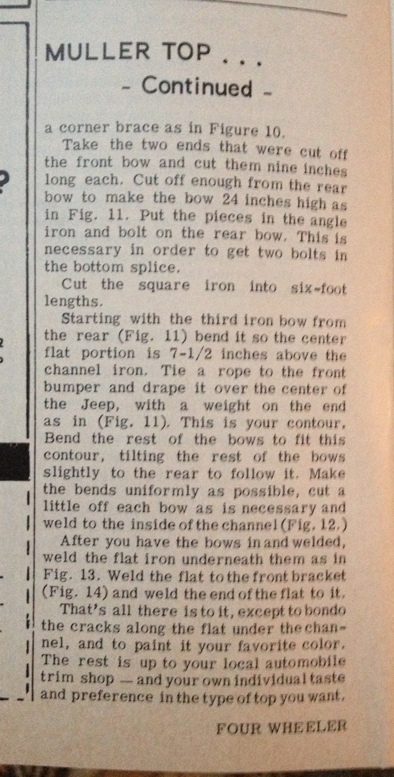
Alex offered this tip on flatfender passenger bars, aka ‘sissy’ bars.

I see on your site quite a few CJ2 or 3 A and even GPW-MBs with “sissy bars” mounted on the dashboards (see photo of red Jeep).

A few years ago, while teaching my niece how to drive, I was in the passenger seat and she drove off a bridge where we fell 9 feet into a dry creek. I got lightly wounded, no problem. The Jeep survived OK.

And here is my point : if I had installed the sissy bar on the dashboard, I today would be for the rest of my life in a wheel chair with exploded knees, because it is just the right heigth to smash them in case of accident (which is not the case in the CJ3 B or CJ5 as their dashboards are quite higher).

Thus to prevent body harm, I recommend to all those who have these grab bars mounted on above mentioned Jeep’s dashboards to move them higher, onto the windshield (see photo of my yellow CJ3 A), where they actually are much more useful.

1950-cj3a-sisi bar-ok

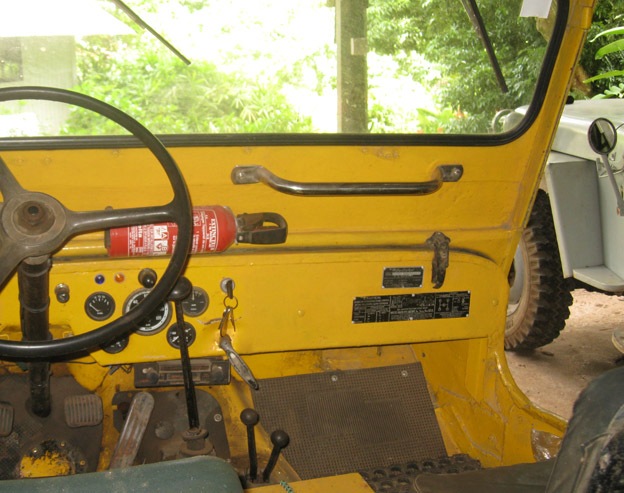
A bar mounted to the windshield is what Alex recommends.

1950-cj3a-sisi bar

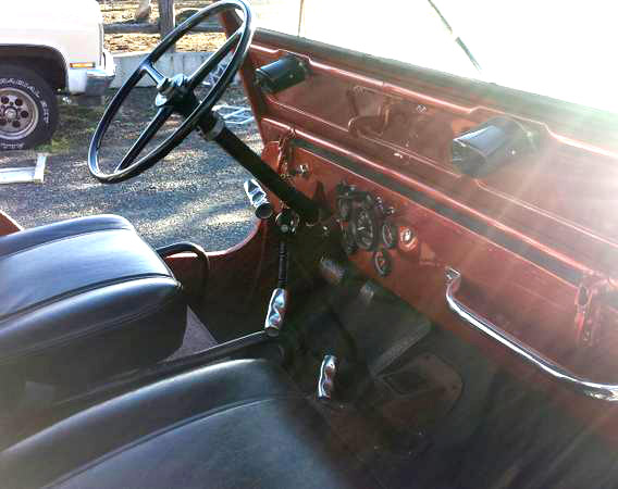
The way some bars are installed.

 
To Top

Transmission ID and More at the Crankshaft Coalition

• CATEGORIES: Features, How To, Website This site contains affiliate links for which I may be compensated.

I happened upon this website while looking for some transmission information. As I scrolled through the page I was impressed with the amount and organization of information. I ended up spending time viewing a bunch of other pages. Since it is a Wiki-based website, people can make corrections and add information.

http://www.crankshaftcoalition.com/wiki/Transmission_identification

crankshaft-coalition-website

 
To Top

How-To Auxiliary Gauge Restoration

• CATEGORIES: Features, How To This site contains affiliate links for which I may be compensated.

dan-gauge-restoration
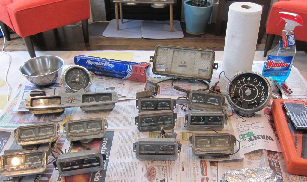
Dan’s had some extra time lately due to a recent foot surgery. He’s used some of that time to put together a “how-to” on auxiliary gauge restoration for the 1950-56 Wagon, Delivery, and Truck and the 1950-1951 Jeepster. He notes they aren’t ‘perfect’, but are a big improvement.

https://www.oldwillysforum.com/forum/index.php?threads/easy-gauge-restoration-and-testing-for-beginners.4435/


To Top

Feb 1949 Popular Science Weatherproofing Hint

• CATEGORIES: Features, How To, Magazine, Old News Articles This site contains affiliate links for which I may be compensated.

Dexter spotted this 1949 issue of Popular Science at a local swap meet the other day.  A reader of the magazine sent in an idea for waterproofing a jeep for only $.75.  Not a bad price.  Probably wouldn’t cost much more today.  Note that it was in 1949 that the CJ-3A came out with a mini gutter to distribute water similar to the role the weather stripping hint accomplishes.  I still have one of those gutters if anyone needs it.

And some other neat hints that aren’t jeep related

Continue reading

 
To Top

Gus and the Model Garage: Gus and the Case of the Councilman’s Car

• CATEGORIES: Artists/Drawings, Books, Features, How To • TAGS: This site contains affiliate links for which I may be compensated.

In this story from Gus and the Model Garage, Gus investigates the centrifugal-advance mechanism. “Gus and the Case of the Councilman’s Car” was published in October 1968.

http://www.gus-stories.org/html/october_1968.htm

 
To Top

Gus and the Model Garage: Gus Sparks a Uranium Hunt

• CATEGORIES: Artists/Drawings, Books, Features, How To • TAGS: , This site contains affiliate links for which I may be compensated.

This is another story about  a jeep from the Gus and the Model Garage series published in Popular Science Monthly.  This particular article was published in June of 1955.  In this story Gus learns about the oil float in the old Willys motors.

http://www.gus-stories.org/june_1955.htm


To Top

Gus and the Model Garage: Gus Goes Hunting … For Trouble!

• CATEGORIES: Artists/Drawings, Books, Features, How To This site contains affiliate links for which I may be compensated.

In this story from Gus and the Model Garage, Gus explains what happens when synthetic rubber gets old.  The story is called “Gus Goes Hunting … For Trouble” and was published in November of 1953.

http://www.gus-stories.org/html/november_1953.htm

 
To Top

Gus and the Model Garage: Gus Helps Land a Big Catch July 1961

• CATEGORIES: Artists/Drawings, Books, Features, How To • TAGS: This site contains affiliate links for which I may be compensated.

From Gus and the Model Garage comes this tale.  It is more adventure story than mechanic story, but it does feature a Ford GP.  It is titled “Gus Helps Land a Big Catch” and published in July, 1961.

http://www.gus-stories.org/html/july_1961.htm

 
To Top

James Breaks the Oil Line Fitting — Could use some suggestions . . .

• CATEGORIES: Builds, Features, How To This site contains affiliate links for which I may be compensated.

Well, we all eventually arrive at one of these places where the unexpected happens, inevitably followed by the ‘what do I do now’ question.  That’s where James is at and he needs a few suggestions.  You might remember James from when I visited his father and him in Denver back in October.

“I was replacing the old inlet oil line into the engine (below the fuel pump). I was loosening the oil line that went into the 90 degree brass fitting oil line bracket (Walck4wd part number 384569) and accidently torqued the bracket. The fuel line came off, but the thread from the 90 degree brass fitting oil line bracket broke off inside the engine in the oil inlet. Great.. So, I bought an extractor from Sears and have been trying to extract the remaining thread left inside the oil inlet (below the fuel pump) with no luck. There is hardly any room to hammer the extractor into the block. So now here I am, stuck. Any idea how to remove the remaining thread? Thanks, James DeBartolomeis”

Here’s a pic:

 
To Top

Shep’s Mock Browning M37

• CATEGORIES: Features, How To This site contains affiliate links for which I may be compensated.

Shep built this custom M37 and thought others might be interested in it.  Thanks for sharing!

Shep writes, “Just wanted to show you some pics of the dummy gun I made a couple days ago.  This dummy gun for the most part is based on the browning M37; which was actually put on tanks instead of Jeeps in Korea.  But I thought it was one of the coolest looking of the Browning .30 cals so decided to use its specifications.  For the main box of the gun, I used an old piece of 1/4 inch 3×5 tubing, which I found was a mistake because almost all other pieces I welded too it was close to 1/8 inch, thus the voltage on the welder had to turned way up to penetrate the box.  The barrel shield was the hardest part.  I had to measure all of the distances correct, and I couldn’t start drilling with 13/16″ bit, I had to work my way up.  The handle on the back is an old axe hand I cut down and threaded.  The bolt shucks back and forth and the sights flip up and down.  The gun pivots up and down as well as side to side.  The pedestal has an ammo can bolted to the side for realism.  I still need to drill the bolt holes for where it mounts in the back of my Jeep, but overall I think this is gonna look good in the M38A1.  The gun also comes off the pedestal, I hope to make an attachable bipod for it in the future.  Hopefully I get pulled over because the cop thinks it’s real, that means I did a good job making it!”

 
To Top

John’s D44 Rear Axle Modification

• CATEGORIES: Features, How To This site contains affiliate links for which I may be compensated.

UPDATE:  I initially had this as a front axle modification, which was clearly incorrect (the lack of a stearing knuckle should have been my first clue!)

Thanks to John for putting together the narrative and the images!

“Thought some other folks might find this interesting, especially those that have swapped to the D44 rear axle.

While trying to cobble some parts together to build a D44 front axle for my CJ6, I  noticed that the GM D44 small bearing spindles that came with the flat top knuckle axles had the same number of  stud holes as the offset D44 in the back of my CJ.  Knowing that the 2 pc. axle shafts were a weak point, I had kicked around the idea of finding a 71′ offset flanged axle, and installing Herms FF Kit. I figured the flanged D44 would be a long shot, and I didn’t really like the tapered shafts in Herms kit, as you have to pull the spindle to get the shaft out.  So,what to do?  I ended up at R&P 4wdin Oregon City, and asked Richard and Paul what they thought about using the GM spindle to make a full float axle kit. At this point, Rich got a twinkle in his eye and asked me to follow him out into the shop.  From some shelf, he pulled a half machined spindle out, and said, “like this?”. Perfect!  This kit probably wont be for everyone, but was a homerun for me. It lets me run the same Ford 1/2 ton hub and rotor as the front(to keep things 5 on 5.5), the same internal splined locking hubs as the front, and GM calipers.  Overall the FF kit added 2″ of width to my rear axle (same as the front), and I got an axle shaft that is full diameter(30 spline inner, 19 spline outer), and is removable without pulling the spindle.  I ended up running a late 70’s Cadillac caliper (that uses the same GM backing plate as the front), and has a E-brake. And all for a little less than a grand.  I hope somebody out there will find this as cool as I did.
Thanks,
John
“im a doughball”
 
To Top

Pounced: Biscuit Finally Has Its Name

• CATEGORIES: Biscuit, Features, How To This site contains affiliate links for which I may be compensated.

It was sometime around mid-summer of last year (maybe earlier) when I started the project to place ‘Lost Biscuit’ on the hood of my jeep. It took a little longer than expected, but I finally did it.
First I had to decide which font to use. Fortunately,  I got some very helpful input along the way from Dexter (thanks) and eventually decided upon the Marker Felt font. Okay, that was pretty easy.

Now, how to get the name on the hood. After hmming and haaaing over how I wanted to attach the name (hand drawn, stickers, stencils, pay someone else … ), I finally decided I would do it myself using paint.  But, I knew my freehand drawing and painting skills froze around the 2nd grade, so this wasn’t something I could improvise. Since I had no immediate solutions, I decided to put the project on hold (which explains the delay).

One day this past December I was watching American Restoration on the History Channel.  The American Restoration show is a spinoff of sorts from the Pawn Stars show and follows various restoration projects from Ricks Restoration out of Las Vegas.  In one of the episodes, called Buttered Up (you can view it here), Rick restores an old popcorn machine.

To repaint the front of the popcorn machine, the painter used a technique that dates back centuries called pouncing. Pouncing? My ears perked up!

Pouncing?  Never heard of that. As usual, my computer was on my lap so I instantly googled pouncing.  I learned,

Pouncing is where pounce — loose graphite or charcoal — is rubbed through a series of small holes punched in a paper pattern to transfer the design to an item to be decorated

Well, I thought that would work for Biscuit’s name.  After some more research, I found out that quilters use pouncing for some stitch patterns.  So, the next day I hit some quilt stores.  As you can imagine, the conversation went something like this,

“Hi, I’m here because I want to paint a name on my jeep,” says I.

Blank stare from cashier, “what do you need?”

“I need stuff for pouncing” says I, remembering now that I probably had not shaved, maybe, not even showered, and most likely wasn’t quite dressed like customers they normally help (however, to my credit, I didn’t have on my garage jeans).

Another blank stare, “you want to do what?” I think she even had her finger ready to dial ‘9’ (and then ‘1’ ‘1’)

It turns out, not everyone knows what pouncing is, even at the quilt stores.  Eventually, after visiting a couple quilt stores, I found what I needed (you will see my pouncing supplies in a picture below).

Here’s the synopsis of this project.

1. Design and Print the template.  Then, since I didn’t have a good awl, I created my own awl out of tape, a chopstick and a long push pin.

2. Next, I attached the template to a piece of cardboard.  Then, I poked holes around the outer edge of all the letters.

3. With the letters outlined, I tested out the template on different materials to make sure it worked.  It turns out pouncing is pretty easy!

4. Selecting paint was the next step. So, I visited my local art supply store and explained to them what I wanted.  They directed me to an Acrylic Titanium White Tube from Windsor Newton. Along with the paint, they also suggested an acrylic spray on sealer and finisher from Americana. I took the paint home and tested it on different materials.  At first, I didn’t like it, because it wasn’t as smooth as the typical oil based house paint I had expected.  Instead, it had texture like a canvas artist would want.  But then, after staring at it a bit, I warmed to the texture, because it gave the name a hand generated feel.

5.  Yesterday, with the weather a little warmer, it was time to paint the name.  I got out my template, my paint, and my pouncing supplies.  I taped the template to the hood and prepared to pounce.

Over the course of my tests, the technique I found most successful for pouncing was not tapping the pouncer, but rather dragging it slowly across the holes.  This kept the paper from popping up and blurring the dots underneath.

The pouncing equipment consists of a pouncer with a ‘handle’ on one side and a soft side on the other.  There’s also a plastic container that can hold pounce.  Lastly, there is the white chalk.

6.  Now it’s time to paint.  I put three coats on each side. This image was taken after the first coat.

This is after three coats.

There is still some small edges that need cleaning up.  Once I do that, I’ll spray it and hopefully that will protect it!

 
To Top

Some Days are Harder than Others ….

• CATEGORIES: Biscuit, How To This site contains affiliate links for which I may be compensated.

The plan was simple, fool proof, and, best of all, idiot proof.  But, alas, not Dave proof. The goal, attach my new ‘ewillys’ stickers to plates and attach them to the sides of Biscuit.

Step One: Have stickers made — CHECK.

Step Two: Cut and shape Ovals out of a street sign (note: not snagged from the subdivision down the street, but from a metal yard) — CHECK.

Step Three: Drill plates for mounting holes — CHECK.

Step Four: Attach stickers — FAIL … well, they are ‘stuck on’, but they have bubbles. That’s $50 down the drain — do over time.

See, had I made step Four “Check the internet on mounting vinyl stickers”, I would have been ok. But nooooooo, instead, I cleaned the plates with a degreaser (should have used soap and water), wiped them dry, and then stuck the stickers (should have sprayed some water and a little soap onto the plate and then squeegeed the sticker onto the plate).

Ok, lesson learned.  So, I bolted the stickered plates onto Biscuit, just for kicks.  I stepped back and took one look and knew I had screwed up, again — twice in one day!  See, I thought that hiding the allen bolts, which are black, along the black lines of the ewillys’ script would hide them. But this didn’t happen.  Instead, they disrupt the eye as you read the logo, both close up and from up to 20ft away.  So, now I’m really ticked.  So I mounted the plates to teach myself a lesson — don’t presume to know what you don’t, check the interet first!

When I cool down, I’ll get some new stickers printed, properly attach the stickers, and widen the bolts left and right.

Below is a blurry pic of the attached sticker.  I’ll replace it with a better one tomorrow  …. Hopefully, I’ll keep someone from making the same mistake 🙂

 
To Top

Want to Ditch that Mechanical Speedometer?

• CATEGORIES: Features, How To, Tips & Tricks • TAGS: This site contains affiliate links for which I may be compensated.

UPDATE: Paul forwarded a pic of the parts for the speedometer:

I’ve included a pic of Paul’s topside dash as an illustration of Paul’s dilemma/solution. You can read all of Paul’s adventures here.

inside2

Paul writes, “I recently hit a bit of a snag with the speedometer sending unit and I thought other Willys modifiers might be interested in the problem and solution.  Since I repositioned the instrument panel above the windshield (the hard top will not be removed and the windshield is not a folding unit) I realized there would be a problem with the mechanical speedometer.

The speedometer drive cable would have to have many tight bends as it snaked it’s way from the rear of the speedometer, down the windshield post, behind the dash and under the body where it would screw into the drive unit on the transfercase.  Taking into account the numerous tight bends, the length of the drive cable and the space necessary for the drive cable routing I figured it would be much easier to use an electric speedometer.  This way I’d only have to string some wires from the speedometer to the sending unit (a hall effect device) attached to the drive gear in the transfercase.

Really rather simple but I discovered the original Willys speedo drive unit was made for a flanged drive cable and the electrical sending unit was made for a square drive cable.  The stub cable supplied with the electrical sending unit is only two inches long but both ends are square so this wouldn’t work with the original shaft in the transfercase.

A friend of mine suggested I talk with the local marine diesel parts guys because he remembered the Detroit diesel engines used similar adapters as tach drives and they might have something which would work.  Less than five minutes after I explained my adapter problem and showed the items I wanted to connect, Jim (the parts guy) found a two inch long flex shaft with a square drive on one end and a round, flanged end on the other.  Not only was this the exact part I needed, the right length, and the right ends, but it was also the right price …FREE!

I realize most of the eWillys folks are keeping their Jeeps closer to stock when it comes to the instrument location, but it’s something to keep in mind if you do decide to go with an electrical speedometer.  Jim sure saved me hours of work since I won’t have to build what I need; I believe a few dozen donuts delivered early in the morning are necessary as a special thanks.  THANKS JIM !!!”

 
To Top

Devon’s Power Steering Setup

• CATEGORIES: Features, How To This site contains affiliate links for which I may be compensated.

Greg asked for a few pics of the Steering combination on the Eller’s Jeeps, so Randy climbed under Devon’s Jeep to snap a few for us. Thanks Randy!

Here is Randy’s description, ”

I took a few pictures of the Saginaw steering setup in Devon’s MB but they were mostly taken from below because of his winch plate covering the top.  It is a little unclear just how it all works without the top view.

Dusty will be bringing his CJ2A back up here in a few weeks and I think it will be easier to get good pictures from his Jeep.  It still has the stock column in it which is what Greg is interested in.  I might have a spare steering box mount to take pictures of as well.

Picture 1 was taken from the driver’s side tire.  The frame was plated on the inside with ½ inch steel and protrudes an inch or so below the frame rail.  The outside plate is 3/8 and is what the spring mounts are also welded onto (the Scout II axles require outboard spring mounts).  3 of the 4 steering box mount bolt heads are visible; the 4th bolt was welded inside the frame rail because I wasn’t certain if it would interfere with the spring mount if it passed all of the way through.  The 2 bottom bolts from the steering box mount to the steering box are also visible; the 3rd bolt is visible in picture 005 on the top-front of the steering box.

Picture 2 shows how the steering box mount lowers the steering gear and in conjunction with the drop pitman arm almost eliminates bump steer even though this Jeep has probably 7 or 8 inches of lift.

The long bolt that protrudes down through the frame rail is one of the winch plate bolts and the other one you can see in Picture 3 ties the bumper and spring mount together.  It is a pretty sturdy assembly with the plated frame rails, spring mounts, steering box mount, winch plate and bumper all tied together.  The frame horns had to be cut off to plate the frame rails; the passenger side frame rail was also plated inside and out.  This mount allows the steering arm to pass underneath the stock round crossmember and it works well with aftermarket motor mounts.”

 
To Top

Identifying A Strange Looking Engine Block

• CATEGORIES: Engine, Features, How To This site contains affiliate links for which I may be compensated.

Brian wrote me asking if I knew what type of engine this was.  He pulled it out of a old WWII Jeep and didn’t recognize it.  He wrote that the Head cast was #634816 and the block casting#630282. In particular, he noted the exposed cylinder tubes.

I told him I didn’t know what it was, and confessed that I had never worked with any MB/GPW motors, but I would do my best to figure it out (I do enjoy a good internet hunt). After searching through various images I could see it was similar to a MB and GPW motor, but was also different.

For example, you can see examples of GPW heads here at Dino’s site and though it looks similar, it’s missing various features.  Here is an example of MB block.  In fact, if you go here, you can review all kinds of WWII engines.

After trying various keyword images searches, I tried typing in the casting numbers and that is when I discovered that the head was a pre war head from a Willys Model 37. So, then I looked at prewar Willys.  On this page http://clubs.hemmings.com/clubsites/wocv/willywilly/willywilly.htm on the fourth pic down, you can just make out, just below the distributor, similar indentations on a 1938 Willys.  Here is a better look at a prewar block.

 
To Top

Paul Re-plates His Plates

• CATEGORIES: Features, How To • TAGS: This site contains affiliate links for which I may be compensated.

Paul continues to make progress on his build, though he does have a habit of becoming side-tracked with wood projects (if I am a Foodie,  he is a Woodie).

Paul writes, “The local exotic wood store has been letting me pick over the wood shipments right after they’re unloaded and this has caused some trouble with overheating my credit card.  While I’m still making progress on the never ending Willys project, money has been in short supply so many of these projects have to be low buck items.  One of the cheaper but necessary jobs was to repaint the brass data plates (a total of six plates) originally installed on the M 38.  While I really wasn’t looking forward to working on these plates ( lots of trouble for very little progress) I felt the appearance of the Willys would be improved by having bright and shiny data plates installed on the heater duct below the base of the windshield.

I use a really strong liquid paint stripper to remove the original black paint from the data plates. After the paint is gone I do a chemical wipe with lacquer thinner then gently rub the bare brass with a fine grade scotch pad before doing another chemical wipe followed by the spray can black. Cheap, easy, and quite time consuming but the finished plate looks pretty good.

While it isn’t difficult to redo these data plates it is real easy to screw up the paint (once the new paint is applied) while cleaning off the lettering and then have to start all over again.  I’m using rattle can glossy black spray paint to apply two light coats on each plate and I let them dry for one day after the second coat.  After the paint is dry I very carefully block sand the plate with 400 grit sandpaper with the plate supported on a thick, flat surface.  I’m using a 3/4 inch thick slab of granite (it’s flat and cheap) so if I didn’t damage the paint during the sanding process I spray a very light coat of clear over the data plate and let it dry for another day.  Don’t spray a heavy coat of clear, it lifts the black paint which results in more clean up time and then you have to start all over.  I figured this out the hard way so you wouldn’t have too.  Geeze, what a guy!

Anyway, if things went well you should have a new appearing data plate to attach to your Willys.  I’m still working on the remaining four plates because I got a little careless while sanding  but the first two plates look pretty good.  I’ve attached three pictures showing the stages of data plate repainting.

1. Cleaned Plates with paint removed.

2. After paint is applied.

3. After paint is lightly sanded off.

 
To Top

Sam Gives Craig’s CJ-3B a Lift

• CATEGORIES: Features, How To • TAGS: This site contains affiliate links for which I may be compensated.

(Sam, feel free to correct if I have erred with any of my descriptions!)

Sam’s been keeping busy working Craig’s CJ-3B.  For example, Craig was complaining that the brakes didn’t work real well.  So, Sam took a close look at them and discovered that the jeep was only stopping with one brake!  Two of the brakes were completely rusted up and the third brake had suffered a pinched line!  So, Sam obtained some brakes off of a Wagoneer (shoot, I can’t remember the details Sam!), installed those and rebuilt the lines.  Now it “stops on a dime with 9 cents change” as Sam says.

Another project Sam tackled was the springs.  The ride was hard as a rock.  Sam told Craig he had a pretty easy solution.  Instead of installing new springs, they just needed to pull the leafs apart, clean them up, install new bushings and shackles, and then add a liner between the springs to help quiet the ride and improve the action between the springs.  So, Sam put everything back together, saving Craig plenty of money in the process, and the ride improved immensely.

A third project Sam tackled was a lift:  Craig wanted the jeep to ride slightly higher, but not as high as a SOA would have been.  Instead of using longer shackles, Sam suggested simply adding some blocks between the frame and spring holders.  This would provide the lift, but negate the need to change the axle angles.  Below are some pics of the finished lift.  During the process, Sam also installed new shock mounts in the middle of the frame, which allows for the use of stock shocks.

The blocks were made with 2.5″ x 2″ x 3/16″ square tubing that has been capped on each end.  Below pre-paint finished product.

Here is the post paint result of the front hanger (note the color is actually black, but the light faded the color)

You can see the homemade shackles that Sam built which utilize the horizontal piece in the middle. This helps reduce spring sway.  He prefers to keep the shackle as short as possible to additionally remove sway.

Here’s a shot of the front of the rear spring.

This shows the ‘new’ brakes, but does not show the lowered top shock mount.  It also doesn’t show the updated Rack and Pinion system which should be completed soon (here are some early images and discussion of the process).

 
To Top

Stitch Welding

• CATEGORIES: How To This site contains affiliate links for which I may be compensated.

Someday, I look forward to learning how to weld better; I’d especially like to work with MIG and work on my TIG (I actually have a rudimentary setup, but haven’t done much with it yet).  So, I’d hardly classify myself as a welding expert (though with two pieces of clean metal I can make a pretty nice stick bead).

Until, if ever, I master welding, here are a couple threads that discuss welding sheet metal together for body repair. If you have any other great, helpful threads, let me know and I’ll add them here.

http://weldingweb.com/showthread.php?t=39466

http://weldingweb.com/showthread.php?t=43249

 
To Top

Sears Allstate Locking Hubs

• CATEGORIES: How To This site contains affiliate links for which I may be compensated.

With Steve’s help, I have obtained some rare images of the disassembly of a Sears & Roebuck Allstate Locking Hub.  Accompanying them is a rough guide.

Here, the bolts are being removed:

Here the bolts have been removed.  Now, the big ring must be removed.

You need to get a hold of the ring and flexing it inward to get it out of the channel.

Here is the cap being pried out:

The ring holds in the four rectangular blocks that engage in the cams inside the cam to switch from locked to unlocked. After that, you’ll need snap ring pliers to remove the ring with the two small holes that you can see in the center around the spline.

Here’s another angle:

Here the parts are getting cleaned:

Shows a box with all the parts from both sides (two assemblies):

 
To Top

Gary’s New Bell Crank

• CATEGORIES: How To, News, Vendors This site contains affiliate links for which I may be compensated.

Do you have a problem with your Bell crank getting a little loose, affecting the steering on your old flattie?  But, you don’t want to go through the mods necessary or alter the originality of  the steering?

Gary’s friend Lawrence has developed a great solution.  Lawrence Elliot theorized that that the bell crank could be machined in a way to accept tapered roller bearings.  It is then fitted with a pin style adjustment.  As you can see in the pics below, the final product looks simple and slick.

If you are interested in having Lawrence build you one of these, you can contact him at 828-287-5275.  Thanks for sharing this great idea!